Clock Man - Eurorack Master Clock Module
If you need information about the hardware visit the page for the VMC-system.
If you want to buy the module please visit the order page.
The software Clock Man provides two functions:
- it is a master clock generator for MIDI-Clock and DIN-Sync.
- it is an editor for the module Clock Boy
The software is published as open source under the creative commons license "by-nc-sa 4.0"
- Download the latest stable Version of the Arduino code.
Clock Man - Users Manual
Firmware Version 0.5
Clock Boy Hardware Version 0.6
Quickstart...
...for those, who think they don't need manuals:- The function of the buttons and the data selector
Mode Buttons Function Parameter Select Mode Start Sends a MIDI Start Signal
Sets the DIN-Sync start/stop signal to high.Stop Sends a MIDI Stop Signal
Sets the DIN-Sync start/stop signal to low.Enter Switches to edit value mode Data, turned
Selects the parameter page
Data, pressed
Not in use Edit Value Mode Start Sends a MIDI Start Signal
Switches the DIN-Sync start/stop signal to high.Stop Sends a MIDI Stop Signal
Switches the DIN-Sync start/stop signal to low.Enter
Writes the selected value to the EEPROM
and returns to parameter select modeData, turned
Selects the value Data, pressed and turned
Tempo: increase/decrease ten times
ClockBoy parameters: Sends the current value to ClockBoy
- Good Luck :-)
Installation
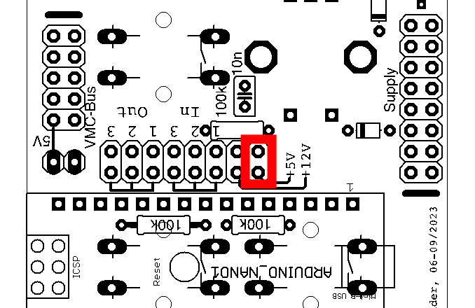
As first step you have to define by jumpers which power supply line is used:
- Your eurorack does not provide +5V, so you use the +12V
line:
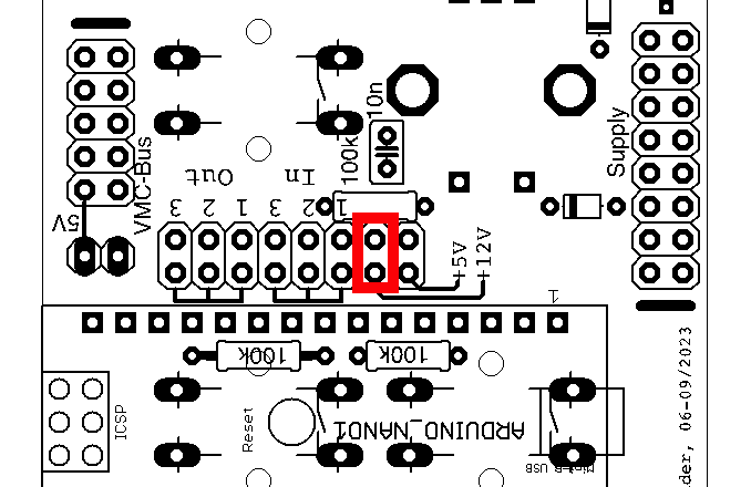
- Your eurorack does provide a +5V line. Then set it like
that:
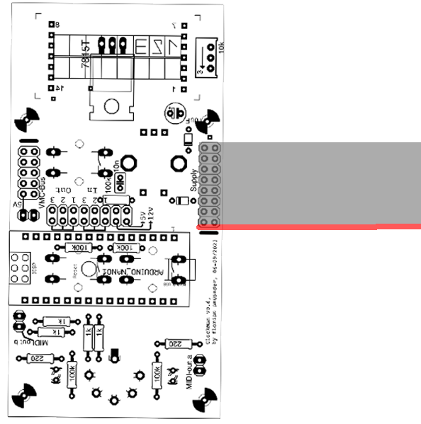
Only connect the module to the power supply if the power switch of your euro rack frame is switched OFF!
Pay attention to the alignment of the cable! The cable must be laid in such a way that the red stripe points in the direction of the marking at the pin header:
To enable the MIDI out on the 5-pin socket of the module you have to set the two jumpers near the DIN socket:
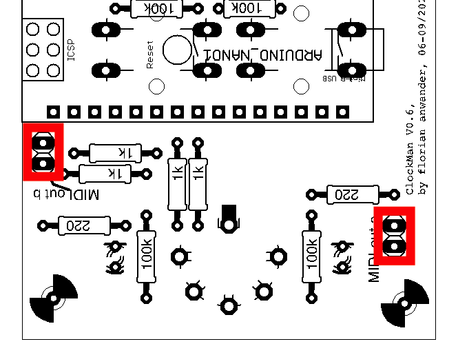
If you connect a DIN-Sync device to the 5-pin socket, it might be possible that the MIDI-signal on the socket troubles the DIN-sync device. In this case remove those two jumpers. We tested with various Roland® devices and with a Jomox® XBase09, and none of them had problems.
When you have finished those settings, mount the module[s] in your euro rack frame
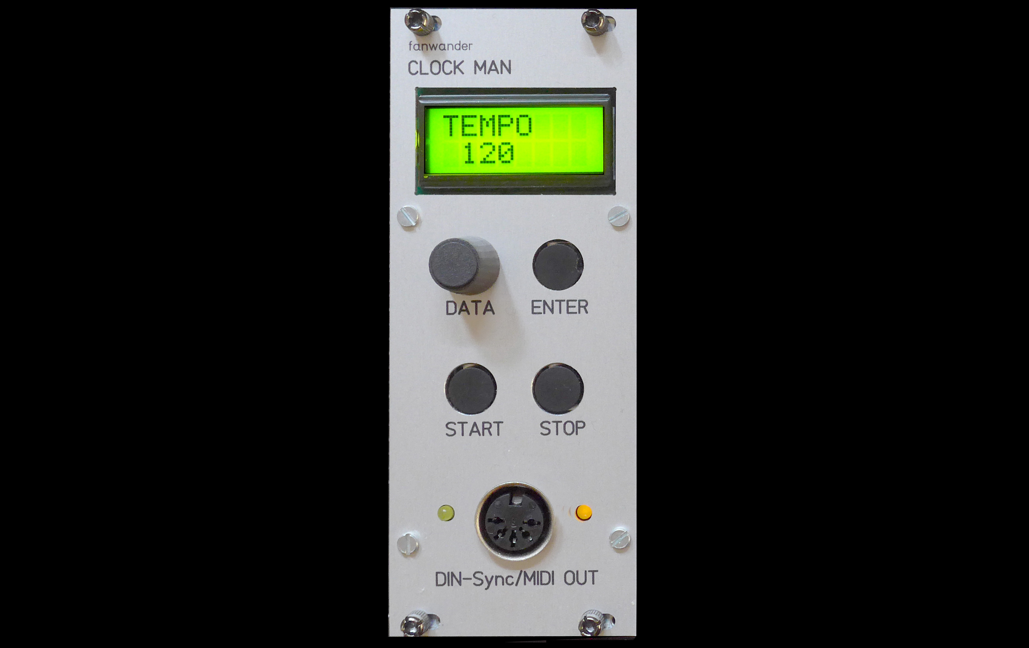
Now you may switch the power of your euro rack frame on. The display should show the name of the module and the software version.
| CLOCKMAN V1.0 |
After one second the display should switch to the tempo display
| TEMPO 120 |
Connections with External Devices
Basically you will have a device which receives MIDI-Clock or DIN-Sync. We call this the MIDI-"Slave".
The connections between the ClockMan and the Slave depend on the functions which the slave requires. Details will follow below.
Establish the following connections:
ClockMan 5-Pin-Out <-> Slave MIDI-In.
or:
ClockMan 5-Pin-Out <-> Slave DIN-Sync-In.
Be sure to enable the clock input at the "Slave" device. On Roland® gear usually a switch on the rearpanel had to be set to "input".
If you want to connect the ClockMan with any other of our devices like MIDI-ITO, ClockBoy or VMC, then please read the following chapter of this manual.
Connections with modules of the VMC System
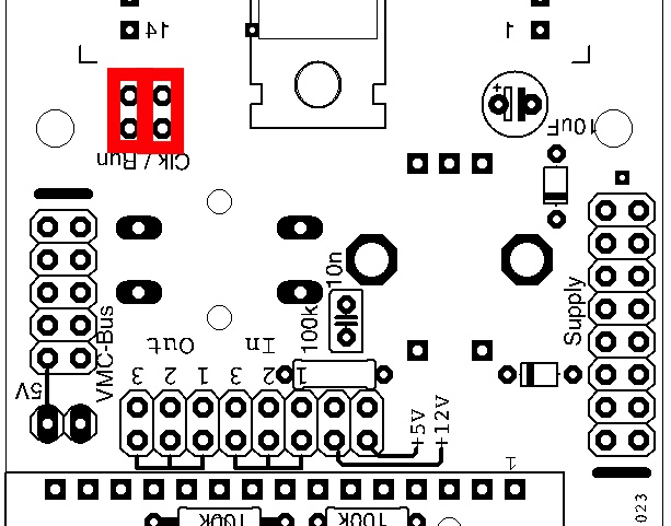
The ClockMan can communicate with other modules of the VMC system via the VMC bus. Two connection types are available for this purpose:- The ClockMan can send the clock signal and/or the start/stop
signal of the DIN sync output on line 1 or 2 of the VMC bus. For this
purpose jumpers have to be set on the pin header pairs above the VMC
bus connector.
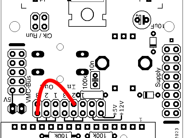
- In addition, the ClockMan can send the MIDI clock signal to the
MIDI lines of the VMC bus and receive MIDI messages on one of the three
MIDI input lines. ATTENTION: Because the potential receivers of the
MIDI clock messages expect the MIDI clock on their input, the MIDI out
of the ClockMan must be connected to a MIDI in(!) line of the VMC bus.
PLease obey the setting in the following picture: one side of the
jumper cable sits on any of the three "Out" pins closer to the Arduino, The other end of the jumper cable sits on the one "In" pin labeled with the number of the bus you want the clock send to (in the example the clock is sent to bus #2).
The basic setup is done now.
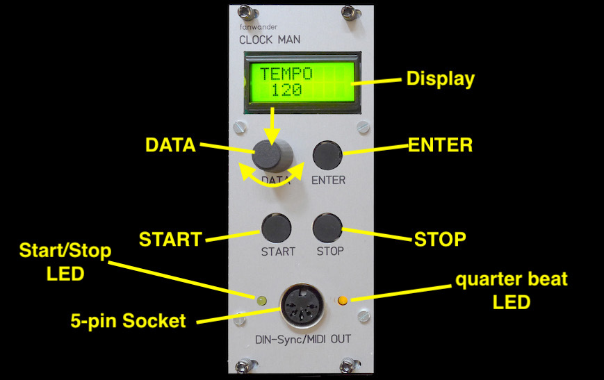
Controls and Connectors
Operation Modes
The ClockMan generates signals for clock, start, or stop at any mode. You may hit START or STOP at any time no matter whether you edit a parameter or not.MIDI clock and the signal on the clock pin of the DIN-Sync is generated continously as soon as the modul is powered up. The right LED will blink at quarter beats.
Pressing the START button sends a MIDI start command and sets the start/stop pin of the DIN-Sync to high (= +5V). Pressing the STOP button sends a MIDI stop command and sets the start/stop pin of the DIN-Sync to low (= 0V). The left LED will be lit when the DIN start/stop pin is high or a MIDI-start has been sent respectively.
Beside that the ClockMan has two modes of operation:
- In the "Parameter Select Mode"
the selection the
various parameters that shall be edited is done,
- In the "Value Edit Mode" the actually selected parameter is set to a dedicated value and written in the internal memory. Parameters that affect the ClockBoy are not stored in the ClockMan (but in the ClockBoy)
Parameter Selection and Editing Parameter Values
IMPORTANT
NOTE: most of the parameters do NOT affect the ClockMan itself, but
only a ClockBoy (if connected with the ClockMan). In software version
0.6 only the parameters "Tempo", "Channel" (and "MIDI Thru" beginning with V0.7) affect the ClockMan!After powering up ClockMan shows the parameter "Tempo". The upper line of the display shows the parameter name, the lower line of the display shows the value.
Turn the endless dial DATA to select the other parameters:
|
<-> |
|
<-> |
|
<-> ... |
To change the value of a parameter press ENTER. The lower line of the display will have now square brackets. Use the DATA dial to select the value.
|
<-> |
|
<-> |
|
<-> ... |
This only selects(!) the value. The parameter still is at the old value. To accept the selected value, either push the knob of the DATA dial or press the ENTER button. Pushing the DATA dial remains in the value edit mode. Pressing the ENTER button returns to the parameter select mode.
Editing the "Tempo" works a little differently. To set another tempo choose in parameter select mode the "Tempo" page (who would have guessed...). Then press ENTER. The beats per minutes value is displayed in square brackets. When you turn the DATA dial the displayed value will change by one. If you press the DATA dial knob while turning the dial, the displayed value will change by ten. In both cases the clock generator will remain at the old tempo. If you now press ENTER, the clock generator immediately changes its tempo and you exit Value Edit Mode.
Often, however, you don't want such a hard tempo change. You can achieve a smooth transition by holding down the the ENTER button, while turning the DATA dial. The change-by-ten trick also works with the ENTER button held down. As soon as you release the ENTER button you exit the Value Edit Mode with the smoothly set tempo
List of the available Parameters:
- "TEMPO": select the speed of the generated clock signal
- "DIVIDER": -> ClockBoy parameter (*)
- "SHUFFLE": -> ClockBoy parameter (*)
- "RST-MODE": -> ClockBoy parameter (*)
- "BEAT-1": -> ClockBoy parameter (*)
- "DIN/MIDI": -> ClockBoy parameter (*)
- "CLK-GATE": -> ClockBoy parameter (*)
- "CHANNEL": enables sending commands to the ClockBoy, selects the MIDI-Channel for this.
- "MIDITHRU":
determines the MIDI Thru handling if the ClockMan reads a MIDI-In
signal via the VMC-bus. (implemented not before v0.7)
Now the detailled desciption of the ClockMans parameters.
(*) For the parameters affecting the ClockBoy please see the ClockBoy manual.
TEMPO
| Value | Comment |
| 20 - 250 |
Turning the DATA dial while holding down the dial knob changes the value in steps of ten. This function is disabled for values above 240 and below 30. Example: You can go from 53, 43, 33 down to 23 in steps of ten, but then you must release the dial and set the remaining values in steps of one. |
CHANNEL
| Value | Comment |
| 0 | The
ClockMan will NOT send MIDI control change data for the ClockBoy. This
will be necessary if one of your "slave"-devices reacts on MIDI CC
between #70 and #76 |
| 1 - 16 |
This has two functions:
|
MIDITHRU
not available in Version 0.6| Value | Comment |
| OFF |
Incoming MIDI-Data are not forwarded to the Output |
| ON |
Incoming MIDI-Data are forwarded to the Output. ATTENTION: This includes incoming MIDI clock or start / stop commands too! Be sure that the MIDI device from which the ClockMan receives the MIDI data does NOT send MIDI-Clock!!! |
All product names and brand names beside “ClockBoy”, "ClockMan", “VMC”, "MIDI-ITO", and “fanwander” belong to the corresponding owners. They are mentioned only for educational purposes.
All rights reserved, by Florian Anwander 2022 - 2023
© Florian Anwander, 2022-2023 [ imprint/impressum ] [ contact ]