Clock Boy - Eurorack DIN-Sync/MIDI to clock converter
ClockBoy_1.26 is the software for my module "Clock Boy" for Eurorack systems. This page is about the software.
If you need information about the hardware visit the page for the VMC-system.
If you want to buy the module please visit the order page.
ClockBoy_1.26 provides conversion from DIN-Sync clock to MIDI clock and vice versa and to separate clock and control trigger signals. The Clock Boy is NOT an active module. It will not send clock-signals without incoming MIDI clock or DIN-Sync.
The software is published as open source under the creative commons license "by-nc-sa 4.0"
- Download the latest stable Version of the Arduino code.
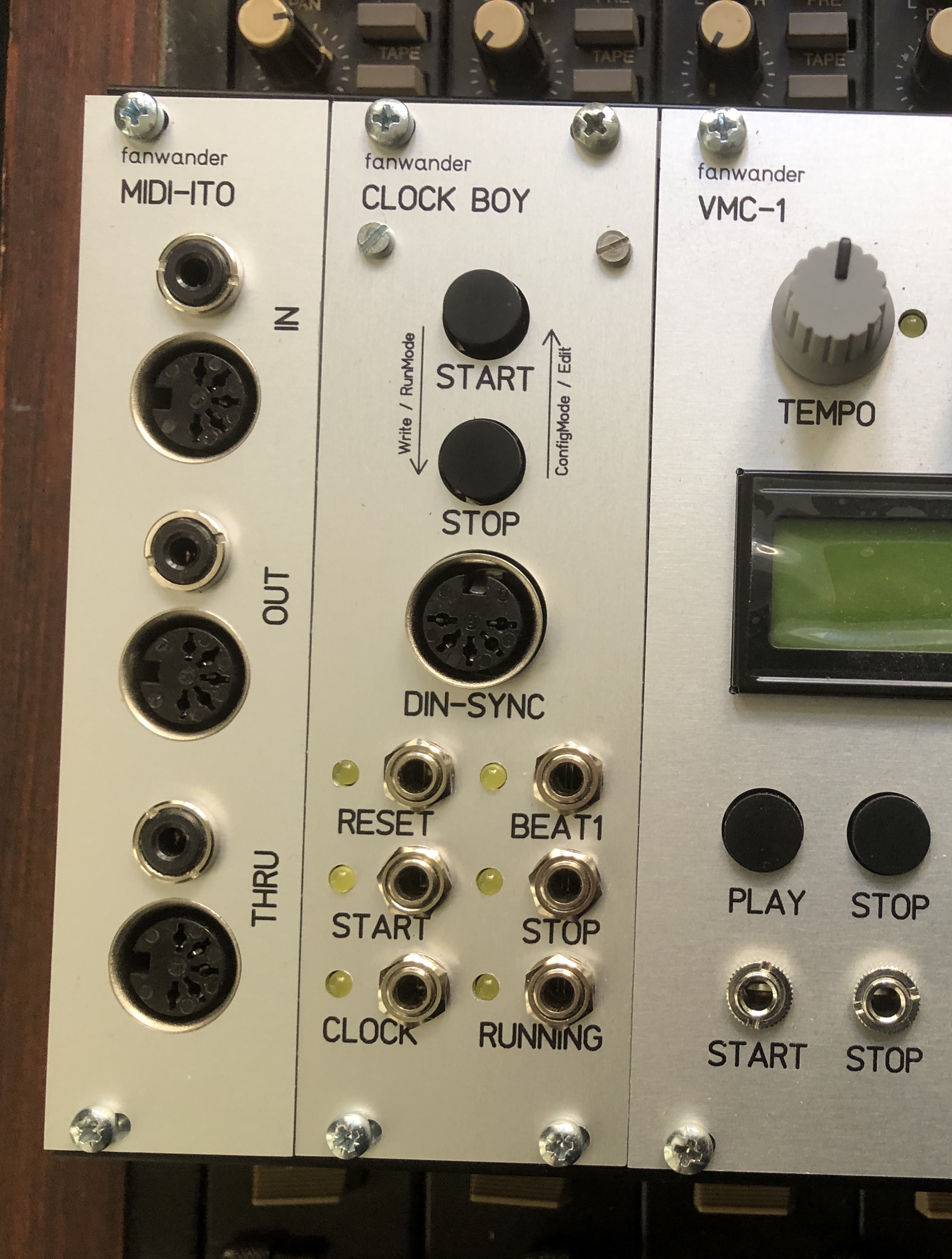
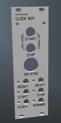
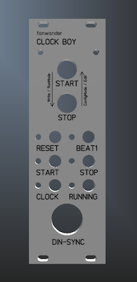
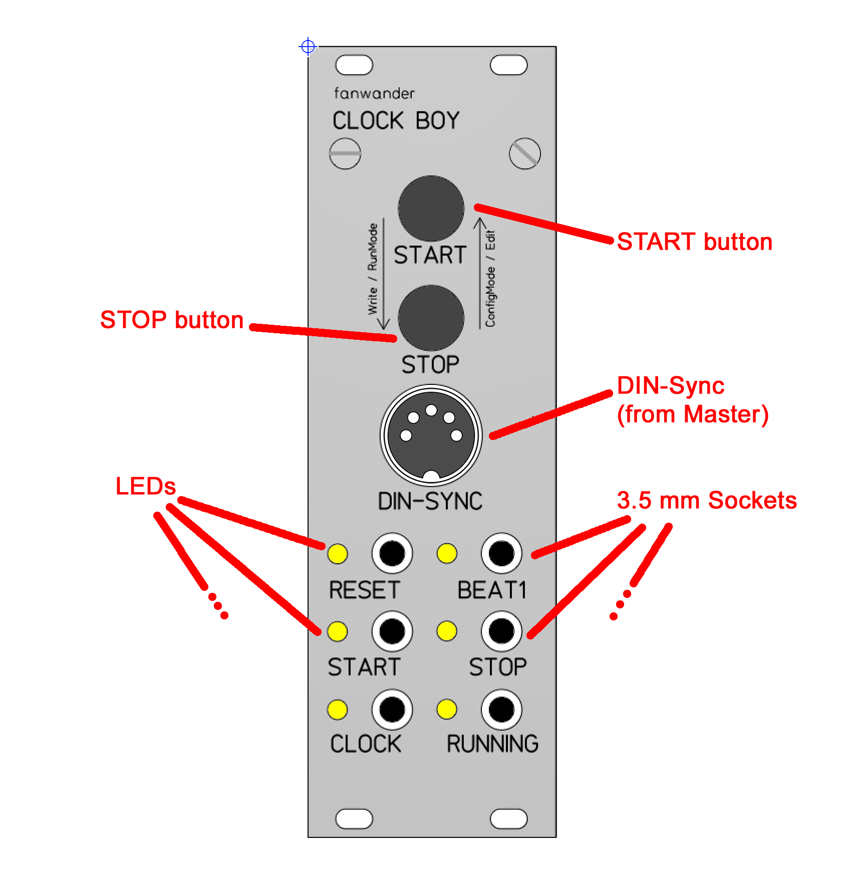
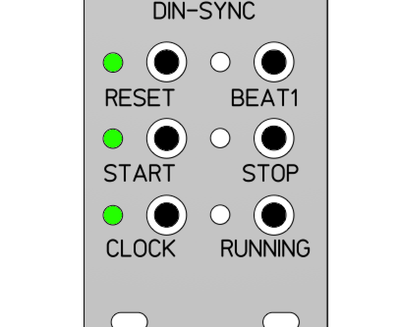
This page shows the panel layout of a prototype series. While testing we found that depending on the mounting positions the buttons should be on the top of the module (mounted in a vertical rack) or at the bottom of the module (when mounted in a skiff). Also the DIN socket should be placed on the other end to make the buttons more accessible. Here are the three versions:
 |
 |
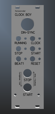 |
| protoype | rack version | skiff version |
The frontpanels for the skiff and rack version are interchangeable. The functionality remains the same.
Clock Boy - Users Manual
Firmware Version 1.21
Clock Boy Hardware Version 3.4
ClockBoy_1.21 is a software for Arduino Nano to run on the Eurorack module ClockBoy. It provides conversion from DIN-Sync clock to MIDI clock(*) and vice versa and to separate clock and control trigger signals Quickstart...
...for those, who think they don't need manuals:-
The function of the two buttons
Mode Buttons Function Run Mode Stop Waits for the next beat1 signal,
then sets run gate to "Low",
sends a stop trigger,
and - depending on the reset mode - a reset trigger.Start Waits for the next beat1 signal,
then sets run gate to "High",
sends a start trigger,
and - depending on the reset mode - a reset trigger.
Hold Stop
Press and Hold Start
Release Stop
Release StartSwitches to parameter select mode.
Parameter Select Mode Start Select the next parameter Stop Selects the former parameter Hold Stop
Press and Hold Start
Release Stop
Release StartSwitches to edit value mode Hold Start
Press and Hold Stop
Release Start
Release StopReturns to run mode Edit Value Mode Start Select the next value Stop Select the former value Hold Start
Press and Hold Stop
Release Start
Release StopWrites the selected value to the EEPROM
and returns to parameter select modeAll Modes Hold Stop
Press Start four times
Release StopDoes a reset to factory values
and returns to run mode
Hold Start
Press Stop two times
Release StartEnables the set-midi-function. To cancel press Stop
- Good Luck :-)
Installation
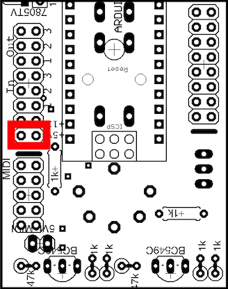
As first step you have to define by jumpers which power supply line is used:
-
Your eurorack does not provide +5V, so you use the +12V line:
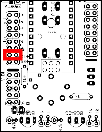
-
Your eurorack does provide a +5V line. Then set it like that:
Only connect the module to the power supply if the power switch of your euro rack frame is switched OFF!
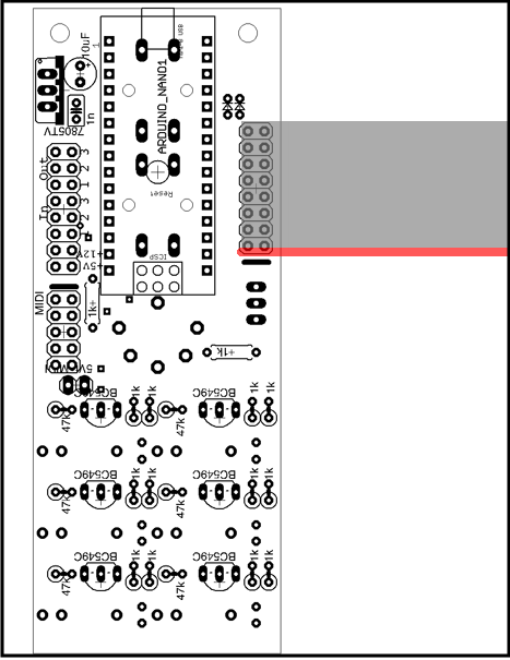
Pay attention to the alignment of the cable! The cable must be laid in such a way that the red stripe points in the direction of the marking at the pin header:
When used with MIDI-Clock a MIDI-ITO module from the VMC-System is required. Connecting the ClockBoy to a fanwander ClockMan module doesn't require a MIDI-ITO module.
Connect the 10-pin header on the MIDI-ITO module with the 10-pin header on the ClockBoy with a ribbon cable. Pay attention to the alignment of the cable! The cable must be connect so that the red stripe points in the direction of the marking at the pin header:
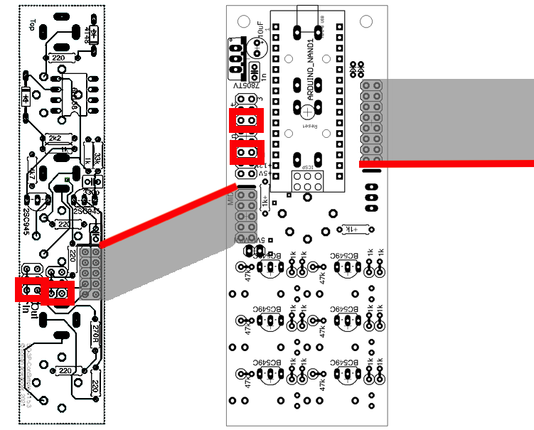
At the MIDI-ITO and at the ClockBoy you have to set jumpers to the same MIDI ports of the VMC-Bus (the picture shows as example the selection for the MIDI port 1)
When you have finished those settings, mount the module[s] in your euro rack frame
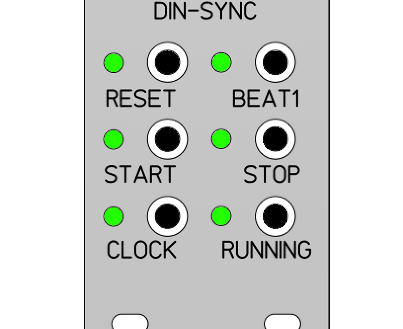
Now you may switch the power of your euro rack frame on. The LEDs of the ClockBoy should light up in a circle three times.
Connections with External Devices
Basically you need a device which sends DIN-Sync or MIDI-Clock data (I will call this "the master") and a device which is controlled by the "analogue" trigger signals from the ClockBoy (I will call this "the slave").
If used with DIN-Sync establish the following connections:
Master DIN-Sync-Out <-DIN-Cable-> ClockBoy-DIN-Sync-In,
and
ClockBoy Clock-Out <-> Slave Clock-In.
ClockBoy ...-Out <-> Slave ...-In.
The connections between the ClockBoy and the Slave depend on the functions which the slave requires. Details will follow below.
If used with MIDI-Clock establish the following connections:
Master MIDI-Out <-DIN-Cable-> MIDI-ITO MIDI-In,
and
ClockBoy Clock-Out <-> Slave Clock-In.
ClockBoy ...-Out <-> Slave ...-In
and optional:
ClockBoy DIN-Sync <-> Slave DIN-Sync-In.
We will go into detail about the connections to the slave devices in the last chapter.
In the factory settings the ClockBoy is configured to receive a DIN-Sync Signal. To configure it for MIDI-Clock please see below.
The basic setup is done now.
Controls and Connectors
This is the logic scheme of the relation between an incoming DIN-Sync Signal and the outgoint signals with 1/16th clock division:
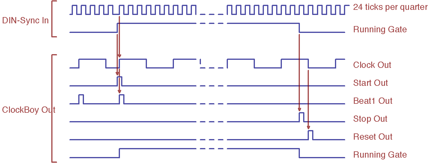
IMPORTANT: Clockboy relies on a continous clock from the master. Whether a slave shall run is determined by the start and stop signals, not by the presence of the clock signal itself. If your master sends the clock signal only when it is running, then the function of Clockboy and the controlled slave devices may be faulty. Especially the reset will not work as intended.
Please read the chapter about various clock and control signals in the euro rack world at the end of this manual.
Operation Modes
The ClockBoy has three modes of operation:-
The "Run Mode" is the normal operation mode in which the incoming DIN or MIDI signal is converted into separate output signals. The module will be in run mode after power up.
-
In the "Parameter Select Mode" the selection the various parameters that shall be edited is done,
- In the "Value Edit Mode" the actually selected parameter is set to a dedicated value and this value is stored in the non-volatile memory of the ClockBoy. The content of the memory will be read out at power-up.
Run Mode
I assume you have connected a DIN-Sync cable coming from a master device, like a Roland® TR-808 or TB-303, that sends a DIN-Sync signal.Also you have connected the 3.5mm output cables with your slave devices. We explain the functions of the outputs below.
The ClockBoy has been reset to the factory settings - see below.
- The CLOCK output will send 1/16th triggers immediately.
Start and Stop control by the master
I assume you have connected a DIN-Sync cable coming from a master device, like a Roland® TR-808 or TB-303, that sends a DIN-Sync signal.Also you have connected the 3.5mm output cables with your slave devices. We explain the functions of the outputs below.
The ClockBoy has been reset to the factory settings - see below (where else... ;-) ).
-
Press "Start" (or "Play" or whatever it is called) on your master device. Now the RUNNING output will become active (=changes from 0V to 8V) and a trigger pulse will be sent by the START output and the
BEAT1 output.
=> your slave device will start playing.
- The BEAT1 output will send a trigger at the beginning of each 4/4-bar.
-
Press "Stop" (or "Halt" or whatever...) on your master device. The RUNNING output will become inactive (=changes from 8V to 0V) and a trigger pulse will be sent by the STOP output; after that stop trigger a
trigger will be sent by the RESET output(*). The CLOCK output will continue to send the 1/16th triggers(**).
=> Your slave device will stop playing.
Start and Stop control by the ClockBoy
We still assume the setting done before. The CLOCK output is sending 1/16th triggers, but the master device is still stopped.- Press "Start" (or "Play" or whatever it is called) on your master device.
=> The RUNNING output will become active (=changes from 0V to 8V) and a trigger pulse will be sent by the START output and the BEAT1 output. -
Now press the STOP button on the ClockBoy.
=> Your slave device will stop playing with the next BEAT1 pulse.
-
=> The RUNNING output will become inactive (=changes from 8V to 0V) and a trigger pulse will be sent by the STOP output; after that stop trigger a trigger will be sent by the RESET output(*). The
CLOCK output and the BEAT1 output will continue sending trigger pulses.
=> Your slave device will pause playing.
- Now press the START button.
-
=> With the next BEAT1 the RUNNING output will become active (=changes from 0V to 8V) and a trigger pulse will be sent by the START output.
=> Your slave device will continue playing in time with the master.
-
Press "Stop" (or "Halt" or whatever...) on your master device. The RUNNING output will become inactive (=changes from 8V to 0V) and a trigger pulse will be sent by the STOP output; after that stop trigger a
trigger will be sent by the RESET output(*). The CLOCK output will continue to send the 1/16th triggers(**).
=> Your slave device will stop playing.
(*)The behaviour of the RESET output depends on the system settings. The description is valid for the factory setting.
(**)The behaviour of the CLOCK output depends on the system settings. The description is valid for the factory setting.
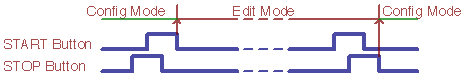
Configure the ClockBoy: Parameter Select Mode, and Value Edit Mode
In the config mode you configure the general behaviour of the ClockBoy.
-
To enter the configuration mode press and hold the STOP button, then press and hold the START button, release the STOP button, release the START button.
=> The LEDs "Beat1, Stop, Running"will blink together two times. You are in parameter select mode now.
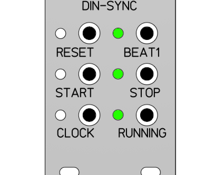
=> One LED which is describing the currently selected parameter will be lit.
-
Now you can page through the parameters using the START and STOP buttons for "next" and "previous". These functions scroll through. Pressing START at parameter 6 will jump to parameter 1.
=> The LED corresponding to the parameter will be lit. -
To change the value of the selected parameter you have to enter the value edit mode: again press and hold the STOP button, then press and hold the START button, release the STOP button, release the START button.
=> The LEDs "Clock, Start, Reset" will blink two times.
=> The LED corresponding to the stored value will blink one time.
=> Now you are in value edit mode.
-
Change the value with STOP (=decrease by one) or START (=increase by one).
=> A double blink of a LED will show the selected value.
-
To leave the edit mode press and hold the START button, then press and hold the STOP button, release the START button, release the STOP button.
=> All six LEDs will blink three times
=> the value will be stored in the non volatile memory
=> you are back in parameter select mode
-
To leave the config mode press and hold the START button, then press and hold the STOP button, release the START button, release the STOP button.
=> The six LEDs will blink in a circle.
=> you are back in run mode.
=> depending on the previous status of the ClockBoy and the actual status of the clock master the CLOCK LED and the RUNNING gate LED will be active.
MIDI Control
The parameters of the ClockBoy can also be set via MIDI Control Change data. The CCs 70 to 75 correspond to the six parameters. CC 76 sets the MIDI channel.In the factory settings the MIDI channel is set to channel 1. To change the MIDI channel,
- press and hold the START button,
- press STOP three times and then
- release the START button.
- => All six LEDs will blink continously.
- Now transmit on the previous MIDI channel on CC 76 the value for the upcoming MIDI channel (starting with value 1; value 0 is ignored).
It is not possible to set the MIDI channel on the ClockBoy itself. Only resetting to channel 1 via factory settings is possible
List of the available Parameters:
- "Clock Division": determines the musical grid sent by the CLOCK output.
- "Swing": sets a swing/shuffle factor for the signal sent by the CLOCK output
- "Reset Mode": determines how a RESET signal is sent.
- "Beat1 Measure": sets the measure for the bar counter of the BEAT1 output
- "Master Source": switches between DIN-Sync and MIDI-Clock as master source.
- "Clock Mode": determines whether the CLOCK output is active all the time or only while the master is running
Now the detailled desciption of the parameters
Clock Division
Sets the Divisor for the clock sent from the clock out put. The divisor will not change immediately but on the next bar (next "beat1" event).| Value | LED that displays the value | Comment | MIDI CC 70, value: |
|---|---|---|---|
| 1/16 | Clock | 0 |
|
| 1/8 | Start | 1 |
|
| 1/4 | Reset | If the barcount is set to 7/8 then the clock will be in the off-beats eacht second bar! |
2 |
| 1/12 | Beat1 | 1/8th triplets (triplet shuffle) |
3 |
| 1/24 | Stop | 1/16th triplets (jack swing) |
4 |
| 1/48 | Running | 12 ticks per quarter; this division can be used for the Roland®CR-68 / CR-78 and some old Korg drum machines |
5 |
Shuffle/Swing
Sets a delay for each second clock tick.
| Value | LED that displays the value | Comment | MIDI CC 71, value: |
|---|---|---|---|
| 0 |
Clock |
This function delays each second trigger of the CLOCK signal. The percentage describes the amount of the delay. Shuffle/Swing work only for the divisions 1/16, 1/8 and 1/4. Neither DIN-Sync out nor MIDI-Out are affected. |
0 |
| 10% |
Start | 1 |
|
| 20% |
Reset | 2 |
|
| 30% |
Beat1 | 3 |
|
| 40% |
Stop | 4 |
|
| 50% |
Running |
5 |
Reset Mode
Determines, when a trigger is sent to the reset output.
| Value | LED that displays the value | Comment | MIDI CC 72, value: |
|---|---|---|---|
| After STOP |
Clock | The RESET signal is sent after the STOP signal. Modules like Doepfer A-154 or A-157 require this mode |
0 |
| With START |
Start |
The RESET signal is sent with the START signal. Modules like the A-155 (without A-154) and many other simple sequencer modules require this mode. |
1 |
| Last 16th |
Reset |
The RESET signal is sent with the last 16th of each(!) bar. This is required by the Vermona MeloDICER. This acts similar to the "After STOP" mode, but repeats each bar |
2 |
Beat1 Measure
Determines when a trigger is sent to the beat1 output. This affects the wait time for the pause mode and also when a change of the clock division becomes valid
| Value | LED that displays the value | Comment | MIDI CC 73, value: |
|---|---|---|---|
| 4/4, 1 bars |
Clock | 0 |
|
| 4/4, 2 bars |
Start | 1 |
|
| 4/4, 4 bars |
Reset | 2 |
|
| 3/4, 1 bar |
Beat1 | 3 |
|
| 5/4, 1 bar |
Stop | 4 |
|
| 7/8, 1 bar |
Running |
If clock division is set to 1/4, then the clock will be in the off-beats eacht second bar! We recommend to use this with 1/8 or 1/16 divisions only. |
5 |
Sync Source
Determines a) which clock source is used and b) whether DIN-out and/or MIDI-out are affected by the pause function.
| Value | LED that displays the value | Comment | MIDI CC 74, value: |
|---|---|---|---|
| DIN-Sync 1 |
Clock | pause function affects analogue clock only |
0 |
| DIN-Sync 2 |
Start |
pause function affects analogue clock and MIDI out |
1 |
| MIDI 1 |
Reset | pause function affects analogue clock | 2 |
| MIDI 2 | Beat1 | pause function affects analogue clock and DIN-Sync out |
3 |
| VMC 1 |
Stop | pause function affects analogue clock | 4 |
| VMC 2 | Running |
pause function affects analogue clock, DIN-Sync out and MIDI out | 5 |
Clock Mode
Determines, whether the clock signal is send also in stop mode or only in play mode.
| Value | LED that displays the value | Comment | MIDI CC 75, value: |
|---|---|---|---|
| Continous | Clock | The CLOCK output will send triggers all the time |
0 |
| Gated |
Start | The CLOCK output will send triggers only if the master is running and the ClockBoy is not paused |
1 |
Factory Reset
The ClockBoy comes with default settings:| Parameter |
FactoryValue |
| clock divider | 1/16 |
| master | DIN-sync 1 |
| shuffle | Off |
| clock out | continous |
| beat-1 | each bar 4/4 |
| reset mode |
Reset after stop |
| MIDI channel |
channel 1 |
For details on the parameter values please see the description in the section config mode.
You can reset the ClockBoy to the factory settings at any time, and from each mode using the following button combination:
- Press and hold the STOP button
- Press the START button 4 times
- Release the STOP button
The Output Signals
All output signals of the Clock Boy are digital. The voltage for the HIGH level at the 3.5mm sockets can be selected by a jumper between either 5V or 12V (in fact the voltages are about 0.2V lower). CLOCK
This is a symmetric pulse signal at the rate determined by the clock division.START
This is a short pulse. It is sent:- if DIN-Sync is master: when the incoming DIN-Sync running-gate does a transition from LOW to HIGH
- if MIDI is master: when an incoming MIDI Start command is received
- when the ClockBoy returns from pause status to the play status
STOP
This is a short pulse. It is sent:- when the incoming DIN-Sync running-gate does a transition from HIGH to LOW
- when an incoming MIDI Stop command is received
- when the ClockBoys changes from play status to the pause status
RUNNING
This output is high in play mode and low in stop mode or pause mode.RESET
This is a short pulse. Depending on the reset mode it is sent with the Start pulse or before or after Stop pulse and after the end of the actual Clock pulseBEAT1
This is a short pulse which is sent after the start pulse with the next clock pulse. The beat1 pulse repeats with each bar count provided in the configuration mode.5pin DIN-Socket
The DIN-Socket acts as MIDI-Out and as DIN-connection (either In or Out, depending on the settings. If an incoming MIDI clock is master, then the DIN-Sync socket acts as an output. The DIN-socket carries the following signals- Pin 1 = Running Gate (Start/Stop)
- Pin 2 = Ground
- Pin 3 = Clock
- Pin 4 = MIDI Tx
- Pin 5 = MIDI +V
The voltage of the DIN-Sync is always 5V.
The MIDI events like start stop and clocktick are translated directly into the corresponding DIN-Sync signal. By Rolands® definition of the DIN-Sync the first clock tick has to be delayed 9ms after the start transition of the "Running" signal. ClockBoy relies on the external source that this source obeys those definitions.
The DIN-Socket carries the MIDI signals on pin 4 and pin 5. In theory this might cause trouble with some DIN-Sync devices (DIN-Sync expects "Fill-In" and "Reset" signals on these pins), but none of my Roland® machines had problems with the MIDI signal on these pins.
If your gear has problems, then use the split adapter.
This MIDI out will work also if a MIDI-ITO module is connected to the ClockBoy.
MIDI Thru
If the master clock is DIN-Sync or VMC-Bus, then MIDI-Thru is disabled.
About Clocks and Control Signals in the Synth World
Clocking is easy - you only have to have luck. That's the summary of our experience with synchronizing various devices in the world of analogue synthesizers and euro rack.Basically there are three tasks to be done in the field of tempo and beat related synchronization of two devices:
1.) The tempo should be the same for both devices.
2.) Both devices should start and stop at the same time.
3.) If both devices were stopped, they should both restart at the same point.
Let's have a look at those three tasks in detail:
1.) The tempo should be the same for both devices.
This should be achieved by the clock signal. Unfortunately there are many types of clock signals and the same amount of varying relations between the clock rate and the musical metrum.The most simple type is: one clock tick corresponds to one musical event. For example: one clock tick = one note. In fact in this case it is not the tempo that is derived from the clock, but each musical event is triggered by an event from the clock. This is valid for most of the simple step sequencers and arpeggiators.
Then there are some devices, where the tempo is not directly related to the individual musical event. DIN-Sync itself is a good example. Described as musical measure this would be 1/96th notes (in written notation this would be a note with four flags and a dot). In fact no drummachine or sequencer will play 1/96th notes. But from this musical measure all useful measures including triplets can be derived.
Another example are quarter-beat triggers. These are often used in devices that also have a tap tempo function. The devices measure the time interval between two tap events or incoming clock pulses and derive their own tempo from this, assuming that the time interval between two taps corresponds to a quarter note. Many guitar stomp boxes understand this kind of signal, but also some euro rack modules like the wonderful "Vermona MeloDICER" do.
2.) Both devices should start and stop at the same time.
This is either achieved by trigger signals for start- and stop or by a continuous signal, we call the "running gate". In communication theory this is the difference between communicating an event (= "I start now") and communicating a status (= "I am running").The "running gate" has the advantage, that it tells about the status of the master even if the slave looses the connection in between. If the slave device reconnects to the master device it knows, whether the master device is still running. The advantage of the event based signal is, that the slave device won't do unwanted restarts in case it looses the connection to the master device. Both methods have their justification and their field of application. So the ClockBoy offers both of them.
Unfortunately there is a third method to communicate starting and stopping: The slave device simply starts as soon as a clock signal appears at its clock input. Those devices are in theory running always, but if there is no clock, they are not able to run. To control these devices the ClockBoy offers the "Gated Clock" mode.
3.) If both devices were stopped, they should do a restart at the same musical point.
This is achieved by a reset signal. This sounds simple at the first glance, but the devil is in the details. Namely in the detail of the receiving device.The question is: on which step of the sequence or pattern does the reset signal set the slave device, and what does the slave device do as soon as it receives the first clock pulse?
We have no chance to list all potential sequencers and drum machines here. Therefore we will explain the problem using the sequencer A-155 from Doepfer and the A-154 control module for the A-155.
If you send a reset command to the A-155 in stopped state, the sequencer jumps to step 1. If you now send a start command and then a clock signal, the first clock pulse will switch the sequencer to step 2. So the sequence will start with step 2. To prevent this from happening, the reset signal must be sent together with the first clock pulse. This is provided in the ClockBoy by the reset mode 2.
By the way, this is not a bug of the A-155. Actually all hardware sequencers without microprocessor behave like this.
Now we do the same with the A-154 (or the A-157 trigger sequencer). The reset command sets the sequence to the last step. If you now send a start command and a clock signal, the first clock pulse will set the sequencer to step 1. The sequence will start as we expect it to. The control module A-154 can do this, because its microprocessor addresses the steps of the A-155 directly.
The operation of the A-154 now seems perfect, but there is a weakness here as well. After a reset command, the A-154 executes the return only when it receives a clock pulse. For this behavior the continuous clock mode is intended, where the clock signal continues to run even in stopped mode. With the A-155, on the other hand, the return jump also works without a clock pulse.
Conclusion: there is no solution that works the same for all devices. Therefore the ClockBoy offers different settings so that you can adapt it to the respective slave device.
All product names and brand names beside "ClockBoy", "ClockMan", "VMC", "MIDI-ITO", and "fanwander" belong to the corresponding owners. They are mentioned only for educational purposes.
All rights reserved, by Florian Anwander 2022 - 2025
©Florian Anwander, 2022-2025 [ imprint/impressum ] [ contact ]