Roland JX3P Modifications
WARNING!!! ALL THESE MODIFICATIONS REQUIRE TO OPEN THE CASE OF THE JX3P. THIS SHOULD ONLY BE DONE BY PEOPLE, WHO KNOW HOW TO HANDLE THE DANGEROUS VOLTAGES INSIDE OF THE JX3P PROPERLY WITHOUT ENDANGERING THE LIFE OF OTHERS OR THEMSELVES!!! IF YOU DON'T HAVE THE REQUIRED EXPERIENCE - KEEP YOUR HANDS OFF!!! DOING THE WRONG THINGS INSIDE AN ELECTRICAL INSTRUMENT MAY KILL YOU OR PEOPLE, THAT RELY ON YOUR WORK. I WARNED YOU. I REJECT ALL LIABILITY FOR ALL CONSEQUENCES OF THE FOLLOWING INSTRUCTIONS!
Since the JX3P is mostly analogue in the sound creation and quite simple digital, there may be done a lot of modifications to the JX3P. The most modifications are put to the schematics, you find on this site.
How to open the JX3P- Lay some soft carpet, foamplastic or similar on the table (like in http://www.florian-anwander.de/roland_jx3p/renovation/images/100-0016_IMG.jpg)
- Place the JX3P on the table in that way that its rear side laps over the table for about 3 cm. (to my experience it is not recommendable to place the JX on its face, because the bender may break inside the frontplate)
- Unscrew the five screws at the bottom rear side. They have a lenght of about 2 cm.
- Store the screws safely.
- Place the JX3P normal on the table.
- In the black plastic side panels are two holes. 1.5 cm Inside there are two screws of 1 cm length. Unscrew these screws. If you don't own a magnetized screwdriver, then first unsrew the screws one side until you feel them going through the thread, then raise the JX on the other side until the screws fall out of the holes. Then do the same on the other side.
- Store the screws safely.
- Now lift the top lid with the nobs and place it vertikally at the rear. PAY ATTENTION: the lid is not fixed to the ground plate by a hinge.
- If you want to unmount the keyboard: It is fixed with four larger screws at the wooden bottom plate. If you don't open the top panel, you have to remove also the five screws which hold the front lid.
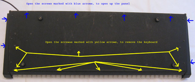
picture in original size
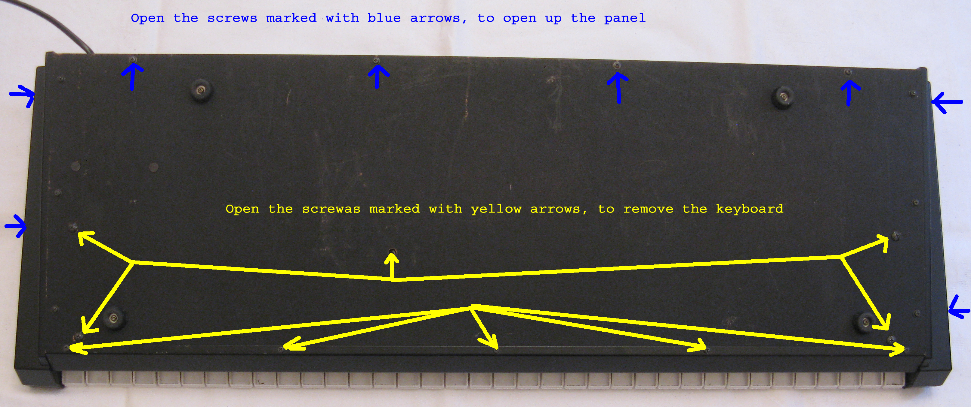
How to close the JX3P
Closing the JX3P after working inside is done in the reverted order basically. The described procedure may sound unnecessarily complicated, but to my experience the threads of screws get worn out, if you do it the usual try-and-seek-and-if-it-doesnot-work-use-force method:
- If you unscrewed the keyboard, then remount it again and tighten the screws.
- On each side unfasten the three screws, which fix the sidepanels to the bottom plate, but don't unscrewn them completely. The sidepanels should only be allowed to move a millimeter
- Place the top lid in its normal position. Take care not to pinch some cables between the rearside and the bottom.
- Get four matches or toothpicks and place them in the screwholes, so they keep the top lid in the right position to insert the screws. It may be helpful to bend the sidepanels slightly to the outside, so you can take a glimpse in the gap between the sidepanel and the frontpanel and find the right place for the toothpick.
- Now one after the other replace the toothpick/match by the screw. Do not fasten the screw completely.
- Insert the five screws which attache the bottom to the rear side of the top lid. Do not fasten the screw completely.
- Now fasten the bottom screws of the sidepanels.
- Fasten the bottom screws of the rearside.
- Finally fasten the screws in the sidepanels.
- Tune the VCF:
set the JX3P to measuring mode (hit Tape Memory, hold ProgKey 5 and hit Tape Memory again); select programm B2; set resonance to maximum, the keyfollow to minimum; play the lowest key and raise the cutoff frequency to a value that results in a tone around 200 Hz; save this Program. If you now hit any key you will see the last 6 LEDS (prg 11 to 16) display, which voice is played. LED 11 is the voice closest to the power supply, LED 16 is the voice closest to the left border of the main board. Now play the lowest voice and adjust with the VR 102, 202, ... 602 the VCF Frequency of the corresponding voice by ear or by a tuning meter. It does NOT matter which frequency exactly the VCF is tuned to, the goal is to tune all six VCFs to the same frequency (that's why you can do it by ear, a tuner is not required).
- Adjust resonance:
Most of the JX3Ps are set to a moderate resonance behaviour. The usage of the VCF as sine oszillator is not guaranteed. This can be achieved by changing the setting of the resonance with the VR 103, 203 ... 603. I suggest to tune first the VCF cutoff frequencies of all voices and then continue with the resonance of the voices. This can be controlled by ear or by an oszilloscope. I used my ears.
I have to add one remark: the organ presets A3 to A5 use much resonance. Especially the preset A3 may sound no longer as you expected it, after you increased the resonance. So you have to decide for your taste, whether the increased resonance makes sense.
- Add tuning for the control amount of VCF control voltage
I did not try this, it is only my suggestion to the courageous ones. The tracking of the JX3Ps VCF chip is quite linear, but the voices may differ among each other. The amount of the tracking is determined by R109, 209 ... 609. If you replace this by a resistor 39k in series with an variable resistor of 10k, you should be able to adjust the tracking. If you try this please tell me the results.
- Split chorus for the use as separated effects unit:
This has to be done on the panelboard: cut the line between C5 and R19/R22. This break will be the input to the chorus. Add a socket for this input at the rear side of the shelf; the socket should be a switching socket. If nothing is plugged in, the broken line should be connected here. If a cable is plugged in, the signal of the cable should be connected over a 10k resistor to C5. If you need a separated output for the chorus, simple connect two sockets to R21 and R23 also here you may use switching sockets to remove the chorus signal from the stereo out.
- Chorus speed:
I removed the brilliance function and am using the brilliance pot for the chorus speed. Simply replace R43 by a 100k or 120k resistor in line with the pot VR1.
The red marks are breaks on the pcb traces, blue are the additional wires.
- Stereo voice separation:
This will only work, if the high pass filter is removed from the signal. It has to be done on the main board. Build a copy of the circuit around IC1, C1 and R7. Leave R1, R2 and R3 (the output resistors of the single voices) on the original circuit and move the R4 to R6 to the new circuit. Connect the output of the new OpAmp (pin 1) to pin 3 of the connector CN1 (the former brilliance line) or do a new wire to the switch board. On the switch board you have to breakup the line between R19 and R22. Connect the signal from the new OpAmp (pin 3 on CN1 from main board or new wire) to R19. Add two resistors with 10k which mix the both signals together to feed the chorus input.
- Replace the Highpass by additional programmable noise:
The detailed description should be taken from the schematics. The principle is: use the VCA, that builds the high pass filter as normal VCA for the noise source. Normally the noise is switched in TR18 by the signal from pin 7 of IC 31. This switching has to be removed: I simply removed TR 18. The VCA circuit is handdrawn on the schematics. As the last step you have to remove in each voice R132, (R232, R332, ... R632) from the connection to R137 (R237...) and connect it to pin 3 of IC103. See the picture.
- External control voltage input for VCF
This input already exists in the form of the brilliance pot. If you use the pot for the chorus speed simply connect a plug to the line which comes from CN1 on the mainboard. If you wish to increase the amount of the modulation, you have to reduce the value of R110, R210, ... to R610 in each voice. To get full modulation amount it must be 4.7 kOhms; the bigger the resistor the smaller the modulationamount of this controll will be. Pay attention: feeding a new fixed CV to the filter might require to adjust the offset setting of the filter (trimmer VR102, 202, ..., 602). I might be necessary to increase also the amount of this trimmer (means: decrease R111, 211, ..., 611).
- MIDI-Through for older models:
Older JX3Ps do not have a MIDI-Thru jack. You simply can break up the two lines to the output jack. Insert a dual switch, that is fed either bye the output liens or by a MIDI-Thru signal which is generated from the MIDI-In by two gates of a 74LS00 and two resistors. Schematic will follow soon. See the picture.
- Transformer Replacement 230V / 117V
I can offer a replacement for the original transformer. It can be used if the original transformer starts to create a mechanical hum or if you want to convert a 115V model to 230V or vice versa.