If you need information about the hardware visit the page for the VMC-system.
If you want to buy the module please visit the order page .
CV2MIDI - Users Manual
Firmware Version 0.22
VMC-2 Hardware Version 1.0
CV2MIDI should be named in fact an2MIDI because it does a generic "analogue to MIDI"-conversion. The software translates incoming voltages, triggers, or gates into various MIDI data.
There are eight so called ports. Each port can do its own type of conversion. The MIDI data sent can be composed from multiple ports.
Most extreme Example:
- port 1 provides the note number,
- port 2 provides the velocity value of this note
- port 3 receives the gate, on which the MIDI note data is sent
Quickstart...
- ...for those, who think they don't need manuals:
Mode Buttons Function Normal Mode Parameter
Selection<- DATA encoder -> Select the parameter of the actual port ENTER button Enables parameter edit DATA button Enables the port selection Press and hold the DATA button
Press and Release ENTER
Release the DATA buttonChanges to system menu Press and hold the DATA button
Press and hold ENTER
Release DATA button
Release ENTER buttonChanges to monitoring mode Port
Selection<- DATA encoder -> Selects the port DATA button Returns to parameter selection Parameter
Edit<- DATA encoder -> Select the parameter value ENTER button Writes the selected value to the memory and returns to normal mode Monitoring Mode ENTER Re-calculate the values DATA button Enables the port selection Press and hold ENTER
Press and hold the DATA button
Release ENTER
Release the DATA buttonDATA button Returns to normal Mode System Mode System Menu <- DATA encoder -> Select the system function ENTER button Enables the selected function Press and hold the DATA button
Press and Release ENTER
Release the DATA buttonReturns to normal Mode All Modes Press the DATA button
Press ENTER
Release the DATA button
Press the DATA button
Release ENTER
Release the DATA buttonResets the program but keeps the custom settings - Good Luck
Now more details for the patient ones...
Controls and Connectors
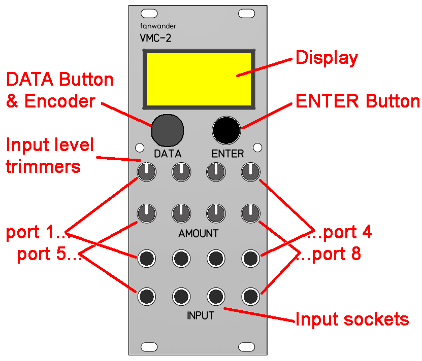
The VMC-2 provides eight so called "ports". Each port has one input socket and one trimmer potentiometer for the input level.
The inputs will recognize voltage changes between 0 Volt and +5 Volt. Incoming voltages that are above +5V or any negative voltages are ignored. If you want to handle any voltages above +5 Volt you have to reduce the input signal with the corresponding trimmer. If you want to handle negative voltages you have to achieve a level shift and possibly some attenuation by using an external offset module like for example the Doepfer A-183-2 (https://doepfer.de/a1832.htm). Also the Doepfer A-138a provides a suitable offset option(https://doepfer.de/a138.htm).
To send MIDI data the VMC-2 requires a MIDI input/output module from the VMC-system like the MIDI-ITO, MIDI-ITOs, or MIDI-3IT with MIDI-OOO. Handling and sending MIDI data via the VMC-bus to other modules of the VMC series is possible too.
Operation Modes
CV2MIDI has two operation modes
- In the Normal Mode the CV2MIDI sends MIDI data according to the incoming voltages.
- In the System Mode MIDI data are not sent; generic settings are done instead.
Normal Mode
Select a parameter
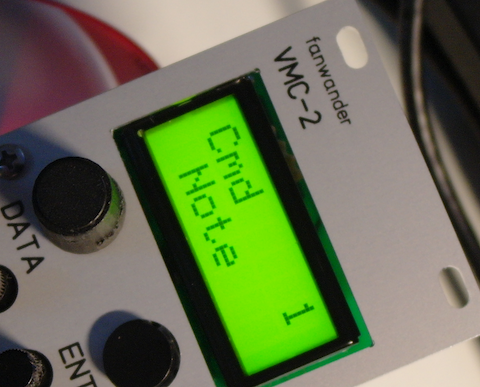
In normal mode the display shows in the top line the parameter (in the example "TYPE") and the number of the selected port (in the example "1"). In the bottom line the value of the selected parameter is displayed (in the example "Trigger").
|
TYPE 1 Trigger |
The DATA encoder selects the parameters for the actually selected port. Depending on the basic setting of the port there are different parameters.
Edit the value of a parameter
To edit the value of a parameter, press the ENTER button. An angle bracket will appear in front of the value
|
TYPE 1 >Trigger |
Select the value with the DATA encoder. For numeric values which can reach from 0 to 127, you may dial with the DATA encoder pushed. This will increase or decrease the values by 10. When the value is less than 10 before 127 or 0 you have dial in single steps. Depending on the parameters it is possible to dial over from the maximum value to the minimum value.
|
TYPE 1 >Gate |
Press the ENTER button again to write the selected value to the internal memory; the angle bracket will disappear
|
TYPE 1 Gate |
On some places it's possible to read a value from incoming MIDI-Data. Example: to set the note number for a trigger port, you may press and hold the DATA button and send the note from your keyboard, that shall be entby this trigger port. For details see the description of the individual parameters.
Select the port
To switch to another port press the DATA button. An angle bracket will appear in front of the port number|
TYPE >1 Trigger |
Select the new port with the DATA encoder.
|
TYPE >3 CV |
Press the ENTER button again to leave the port selection; the angle bracket will disappear
|
TYPE 3 CV |
Remark: It is not possible to switch the port while you are editing the value of an parameter.
System Mode
To switch between normal mode and system mode(*)
- Press and hold the DATA button
- Press and Release ENTER
- Release the DATA button
The display now will show:
|
SYSTEM: use dial |
Within System mode you have to select a function using the DATA encoder. The various functions require individual handling. Please see the detailed descriptions below.
if you used the opposite order of pressing and releasing button by mistake, you will switch to the monitoring mode (see below). Please check that section, how to leave the monitoring mode
Available parameters.
Depending on the functionality different parameters can be selected / adjusted. The following table lists the parameters for each functionality
Basically there are three types of action:
- "Trigger" sends one single MIDI command if the incoming voltage crosses a threshold level from below the threshold to above the threshold (this threshold level can be defined in the system settings).
- "Gate" sends one single MIDI command if the incoming voltage crosses a threshold level from below the threshold to above the threshold, and a corresponding MIDI command if the incoming voltage crosses a threshold level from above the threshold to below the threshold level. Example: Note On and Note Off
- "CV" translates the incoming voltage proportionally in data values. If the parameter command is set to "CC" or "Note" then a new MIDI command will be sent for each new value. If the command is set to "value" no MIDI data are sent from this port, but the generated value can be used by some other port
| Type | Channel | Command | Parameter1 | Parameter2 | Parameter3 | Parameter4 | Parameter5 |
|---|---|---|---|---|---|---|---|
| Trigger | unused | ClockCommand | On-Command | Enable AllNotesOff |
|
|
|
| Trigger | 1-16 | CC | CC-Number | CC-value / Port |
|
|
|
| Trigger | 1-16 | Note | Note-Number | Velocity value / Port | Note Length |
|
|
| Gate | unused | ClockCommand | On-Command | Off-Command | Enable AllNotesOff |
|
|
| Gate | 1-16 | CC | CC-Number | CC-value(on) / Port | CC-value(off) / Port |
|
|
| Gate | 1-16 | Note | Note-Number / Port | Velocity value / Port |
|
|
|
| CV | 1-16 | CC | CC-Number | Range | Offset | Resolution |
|
| CV | 1-16 | Note | Velocity value / Port | Range | Offset | Resolution | Note Length |
| CV | unused | value | Range | Offset | Resolution |
|
|
The following tables list the possible values for the parameters 1 - 5 for each of these combinations of Type and Command:
Trigger with ClockCommand
| Parameter | Display | values | Comment |
|---|---|---|---|
| On-Command | "OnCmd." | Start / Stop / Continue |
|
| Enable AllNotesOff | "AllOff" | Yes / No | A setting to "Yes" will send an all note off command (CC#-123) after a Stop Command |
Trigger with Control Change (CC)
| Parameter | Display | values | Comment |
|---|---|---|---|
| CC-Number | "Cc#" | 0-127 | Defines which Control Change command is sent use the DATA dial or press and hold the DATA button and send the corresponding CC command to MIDI-in |
| CC-value / Port | numeric value or "port <number>" |
0-127 / Port | To select the port dial up until 127 and then continue with singles steps. |
Trigger with Note
| Parameter | Display | values | Comment |
|---|---|---|---|
| Note-Number | "Note#" | 0-127 / Port 1-8 |
Defines which inote number is sent use the DATA dial or press and hold the DATA button and send the corresponding Note command to MIDI-in values 0-127 set a fix value. Port will use the value generated by the selected port. To select the port dial up until 127 and then continue with singles steps. |
| Velocity value / Port | "Veloc." | 0-127 / Port |
0-127 set a fix value. Port will use the value generated by the selected port. To select the port dial up until 127 and then continue with singles steps. The note-Off velocity is set fix to 64 |
| Note Length | "Length" | 0-16 | This is not a dedicated time, but a generic length value. The absolute range can be defined in the System settings. |
Gate with ClockCommand
| Parameter | Display | values | Comment |
|---|---|---|---|
| On-Command | "OnCmd." | Start / Stop / Continue |
|
| Off-Command | "OffCmd." | Start / Stop / Continue |
|
| Enable AllNotesOff | "AllOff" | Yes / No | A setting to "Yes" will send an all note off command (CC#-123) after a Stop Command |
Gate with Control Change (CC)
| Parameter | Display | values | Comment |
|---|---|---|---|
| CC-Number | "Cc#" | 0-127 | Defines which Control Change command is sent use the DATA dial or press and hold the DATA button and send the corresponding CC command to MIDI-in |
| CC-Onvalue / Port | "OnVal" | 0-127 / Port | 0-127 set a fix value. Port will use the value generated by the selected port. To select the port dial up until 127 and then continue with singles steps. |
| CC-Offvalue / Port | "OffVal" | 0-127 / Port |
0-127 set a fix value. Port will use the value generated by the selected port. To select the port dial up until 127 and then continue with singles steps. |
Gate with Note
| Parameter | Display | values | Comment |
|---|---|---|---|
| Note-Number | "Note#" | 0-127 / Port |
Defines which note number is sent use the DATA dial or press and hold the DATA button and send the corresponding Note command to MIDI-in 0-127 set a fix value. Port will use the value generated by the selected port. To select the port dial up until 127 and then continue with singles steps. |
| Velocity value / Port | "Veloc." | 0-127 / Port |
0-127 set a fix value. Port will use the value generated by the selected port. To select the port dial up until 127 and then continue with singles steps. The note-Off velocity is set fix to 64 |
| Note Length | "Length" | 0-16 | This is not a dedicated time, but a generic length value. The absolute range can be defined in the system settings. A value of 0 (zero) will send the note off command just before the next note. In this legato mode an allNotesOff command will be sent, if the VMC-2 receives a MIDI Stop command |
CV with Control Change (CC)
| Parameter | Display | values | Comment |
|---|---|---|---|
| CC-Number | "Cc#" | 0-127 | Defines which Control Change command is sent use the DATA dial or press and hold the DATA button and send the corresponding CC command to MIDI-in |
| Range | "Range" | 0-127 | Defines into how many steps the full range of 5 Volts will be divided. If the range plus the offset value would become greater than 127, then the corresponding difference will be subtracted |
| Lowest value | "Offset" | 0-127 | Defines the value that is sent out when 0 Volts are reached. |
| Resolution | "Res." | 1-128 | The Resolution is explained below in detail. The display shows a "recommended" value in brackets. |
CV with Note
| Parameter | Display | values | Comment |
|---|---|---|---|
| Velocity value / Port | "Veloc." | 0-127 / Port |
0-127 set a fix value. Port will use the value generated by the selected port. To select the port dial up until 127 and then continue with singles steps. The note-Off velocity is set fix to 64 |
| Range | "Range" | 0-127 | Defines into how many notes the full range of 5 Volts will be divided. If the range plus the offset value would become greater than 127, then the corresponding difference will be subtracted |
| Lowest value | "Offset" | 0-127 | Defines the note number that is sent out when 0 Volts are reached. |
| Resolution | "Res." | 1-128 | The Resolution is explained below in detail. The display shows a "recommended" value in brackets. |
| Note Length | "Length" | 0-16 | This is not a dedicated time, but a generic length value. The absolute range can be defined in the system settings. A value of 0 (zero) will send the note off command just before the next note. In this legato mode a allNotesOff command will be sent, of the VMC-2 receives an MIDI Stop command |
CV with value
| Parameter | Display | values | Comment |
|---|---|---|---|
| Range | "Range" | 0-127 | Defines into how many different values the full range of 5 Volts will be divided. If the range plus the offset value would become greater than 127, then the corresponding difference will be subtracted |
| Lowest value | "Offset" | 0-127 | Defines the value that is sent out when 0 Volts are reached. |
| Resolution | "Res." | 1-128 | The resolution is explained below in detail. The display shows a "recommended" value in brackets. |
How the CV function works - the relation between "range" and "resolution"
Basically, a CV function with Note or CC as a command sends the corresponding command as soon as the input voltage changes. If you set "Range" to 127 and "Offset" to 0, turning the input level produces a glittering glissando of chromatic notes. If you set the "Range" to 13 and the "Offset" to 60, a full turn of the input level trimmer produces a chromatic scale from C3 to C4. This is how it works under theoretically ideal conditions.
In fact, it depends on the "Range" setting whether a change in the input signal should be recognized as a valid value change. At low "Range" settings, small changes in the input voltage can lead to double triggering of the same note, which would lead to new notes at high "Range" settings. For a low "Range" of only one octave, you need a resolution value of 10 or 12, for high "Range" values you need a resolution of "1". If you have a high "Range" setting such as "127" and increase the resolution, the MIDI commands will only be sent on every second change. This results in a whole tone scale for the notes, then a scale of minor thirds, then major thirds and so on. This works like a quantizer, but in quite unconventional scales.
As this can be a little confusing, the display shows a "recommended" value for the resolution in brackets, which is calculated for the current "Range" value. If you select this value, notes or CCs are always triggered to the next note or CC value.
How to adopt the VMC to voltage sources
The VMC-2 offers a monitoring mode for setting the input voltages.- To enter the monitoring mode, press and hold the DATA button, press and hold ENTER, release the DATA button, release ENTER.
- In monitoring mode, two numbers are shown on the bottom line of the display. The left number is the lowest output value, the right number is the highest output value, which both have be derived from the incoming voltage since the last press of ENTER. Please note that these values depend on the "Offset" and "Range" settings for the respective port.
- To redo the measurement, briefly press ENTER.
- To return to the normal mode, press and hold ENTER, press and hold the DATA button, release ENTER and release the DATA button.
- Start in normal mode
- Set the "Offset" parameter on the VMC-2 to "0"
- Set the "Range" parameter on the VMC-2 to "127"
- Turn the input level control fully clockwise.
- Set the VMC-2 to monitor mode.
- Now use your sequencer or keyboard to switch back and forth between the highest and lowest voltage.
- Check the maximum output value.
- If the value is below 127, leave the input level potentiometer at the right stop.
- If the value is 127, turn the input level potentiometer slowly to the left while you press ENTER repeatedly until the value starts to fall below 127.
- Check whether the sent lowest voltage triggers the desired lowest output value (press ENTER repeatedly to reread the value).
- If not, correct the "Offset" value.
- If the "Offset" is already at zero, but the monitor shows a higher value as minimum, then your incoming voltage does not reach 0 Volt as the lowest voltage.
- Then check whether the highest desired output value is actually sent with the highest voltage.
- If the value sent is too high, reduce the "Range" value
- If the value sent is too low although "Range" is set to "127", then the output voltage of your keyboard or sequencer does not appear to reach 5 volts.
You need either a dedicated offset/mixer-module, like the Doepfer A-183-2, or a mixer that handles DC and a voltage source which provides a constant voltage of +2.5 Volt or more (e.g. a logic inverter will output +5V if no inputsignal is given). The Doepfer Mixer A-138 built after 2004 already provides suche a constant voltage on input 1.
- On the VMC-2 set the input level potentiometer of the corresponding port fully clock wise
- On the VMC-2 set the parameter "Offset" to 0 (zero)
- On the VMC-2 set the parameter "Range" to 127
- Mixer: Connect the LFO and the constant voltage to two inputs of the mixer
Offset-Modul: connect the LFO to the input of the offset modul. - Mixer: Turn both inputs of the mixer down,
Offset-Modul: turn the input down and set the offset to 0 (zero). - Set the VMC-2 to monitor mode.
- On the Mixer or Offset-Modul turn the input of the LFO fully up
- Check on monitor page of the VMC-2 the highest value. If this value is below 63 then the full sweep of the signal is below 5V. Remember this highest value
- On the Mixer or Offset-Modul turn the input of the LFO fully down
- On the Mixer or Offset-Modul turn the Offset value up;
- If the highest value created by the LFO was below 63, then set the Offset-amount at the Mixer/Offset-Modul so the VMC-2 now displays the same maximum value
- If the highest value created by the LFO was above 63, then set the Offset-amount at the Mixer/Offset-Modul to 63 displayed on the VMC-2 monitor
- On the Mixer or Offset-Modul turn the input of the LFO slowly up until the highest MIDI command value reaches 126.
- Check now the lowest value of the MIDI command. If it is above 0 then turn the offset a little bit down and increase the LFOs level a little bit.
System Settings
(This section still is under development in version 0.21)
In the System section the various functions are called up by pressing ENTER. Some functions are then executed automatically, other functions will call up additional menues. It is common to all functions that they will return to the first page of the system settings, where no function is called up until it has been selected with the DATA encoder.
Adjust Potis
This is a procedure to adopt the software to the individual potentiometers and to the limiting diodes in the input. How to proceed:
- Do NOT press ENTER immediately
- Remove all cables from the input sockets
- Turn all eight trimmers fully clock wise
- Now press ENTER
You will see how the program very quickly counts up a number from 0 for each port and then displays the word "GOOD!" for one second. The number should not count much further than 150 or 160. If the count keeps going up, check that the trimmer is really set fully clockwise and repeat the process.
The values are stored in the non-volatile memory. Usually this has to be done only once after you mounted the module into your rack. If environmental conditions change (temperature, moisture) or if the module is connected to a different power supply or run only via USB, then re-doing this procedure is recommended.Factory Reset
This will reset the settings of all ports to a factory setting:
| Port | Function |
|---|---|
| 1 | Gate sends Start and Stop |
| 2 | Trigger sends note 36 on channel 10 (BD) |
| 3 | Trigger sends note 40 on channel 10 (SD) |
| 4 | Gate sends Notes on channel 1 using ports 7 and 8 |
| 5 | CV sends CC#=7 (Volume) on channel 1 |
| 6 | CV sends Notes over 5 octaves on channel 1 |
| 7 | CV value, used as note by port 4 |
| 8 | CV value, used as velocity by port 4 |
MIDI Soft Thru settings
This setting is not made per channel, but for all channels in general
| Parameter | Display | values | Comment |
|---|---|---|---|
| Note Thru | "NoteThru" | On / Off (default=On) | Determines whether incoming MIDI note events are forwarded to the MIDI-Out. This will be set to "off" automatically if the "transpose" value is set to "On"! |
| Pitchbend Thru | "BendThru" | On / Off (default=On) | Determines whether incoming MIDI pitchbend events are forwarded to the MIDI-Out. |
| Control Change Thru | "CcThru" | On / Off (default=On) | Determines whether incoming MIDI control change events are forwarded to the MIDI-Out. |
| Programchange Thru | "PrgThru" | On / Off (default=On) | Determines whether incoming MIDI program change events are forwarded to the MIDI-Out. |
IMPORTANT REMARK ON MIDI STREAMS SENT THROUGH THE VMC-2:
The Arduino processor used in this module provides only a small buffer, that stores incoming MIDI data. If this buffer is overloaded, then the system may hang or will no longer react on incoming MIDI events at least. In this case you may do a full restart (Press the DATA button, Press ENTER, Release the DATA button, Press the DATA button, Release ENTER, Release the DATA button).
We do not recommend to feed the CV2MIDI with a MIDI signal coming from a DAW or workstation, which contains a lot of note and controller data on all midi channels. If you want to add the CV2MIDI's data to the MIDI-stream coming from a DAW, then use a separate physical port on your MIDI interface, which provides the corresponding MIDI-data only.
Save settings / Load settings (not implemented yet in Version 0.21)
In theory it's possible to store 3 different settings in the internal EEPROM of the Arduino. Perhaps we will provide this option.
Trigger Level
| Parameter | Display | values | Comment |
|---|---|---|---|
| Trigger Level | "TrigLvl" | 1-126 (default=63) | Sets the value above which an incoming voltage is recognized as active trigger or gate. values close to 0 or 127 can result in "no trigger" or "hanging gate". Please keep in mind that the input level trimmer of a port configured to trigger or gate should be turned up fully clockwise. |
Note Length factor (not implemented yet in Version 0.21)
| Parameter | Display | values | Comment |
|---|---|---|---|
| Note Length Factor | "LengthFc" | 1-20 (default=1) | a numeric factor that determines the maximum length of the played notes, if no gate-port is assigned to this CV-port. The "note length" of the individual ports is multiplied with this factor |
Transpose Enable
| Parameter | Display | values | Comment |
|---|---|---|---|
| Transpose Enable | "Trnspose" | On / Off (default=Off) | determines, whether incoming MIDI note data will transpose the notes generated by CV2MIDI. If transpose is on the MIDI NoteThru will be switched off automatically |
Transpose Center Note
| Parameter | Display | values | Comment |
|---|---|---|---|
| Transpose Middle Note | "TransMid" | 0-127 (default=60) | Determines the MIDI note number that is recognized as "no transpose". |
All product names and brand names beside "VMC", "MIDI-ITO", "MIDI-3IT", "MIDI-OOO", "MIDI-ITOs", and "fanwander" belong to the corresponding owners. They are mentioned only for educational purposes.
All rights reserved, by Florian Anwander 2024
©Florian Anwander, 2024 [ imprint/impressum ] [ contact ]