VMC-System - System Definition
The VMC-System - Introduction
The idea for the VMC-System has its roots in my stage setup. For many years I used a lot of little devices to combine various synths, sequencers, drum machines and my modular system: master clock generator, sync converters, restart boxes, clock shufflers, clock dividers - countless little boxes, each with its wallwart and even more cables. Preparing my setup on stage was quite a "hack job" each time.One day I started to develop a small clone of the JX-3P sequencer as a standalone MIDI device. Since making suitable enclosers is not my strongest ability I decided to add it to my euro rack skiff. And because I needed three of these sequencers but wanted to use only one keyboard, I built an input module with switches to select the three sequencers, and I made also an output module for all three sequencer. This was already the hardware base for the VMC bus system, but I still did not think it as a universal system. But thinking on and on (and while talking in forums and maillists) I got the idea that this could be the base for a generic system that solves my "hack job"-problem on stage by mating the modular idea with the idea of MIDI-data handling and generic clock-handling.
The VMC-System - Overview
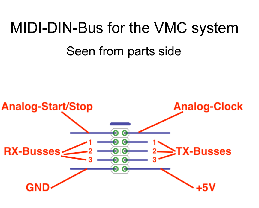
The core of the system is a signal bus - in reality a simple flat cable. It provides:- +5V supply power (and ground of course)
- three pairs of MIDI RX/TX lines (I will explain soon)
- one clock line
- one start/stop line
- Interface modules like MIDI-in or out, DIN-Sync in/out, or 16th-Clock-out
- Data handling modules like the mentioned sequencer, an arpeggiator, a clock-converter, CV-to-MIDI-Cc mangler, velocity-compressor, clock-shuffler, polyphonic scale quantizer, ... zillions of ideas come to my mind.
Details about the bus
- The +5V line is not intended to supply many modules. It is intended to provide the voltage which is required for the MIDI-In/Out/Thru connections. It may also supply one or two modules with very lower power consumption, like a simple MIDI Thru box. If a module provides a 5V supply on this pin, then it must be possible to disconnect the bus pin from the internal supply of the module using a jumper (the first batch of the VMC-1 does not have this split!).
- The GND line is laid out only to carry the corresponding currents. It is intended only as digital ground. It must be separated electrically from the panel: use mini-jacks with isolated ground; do not connect pin 2 of the MIDI-IN DIN-socket to this ground. If DIN-sockets are used for DIN-Sync connections, then pin 2 must be connected to this ground.
- The MIDI RX lines are fed from an opto coupler at the MIDI-IN or directly from another MIDI signal generator. They must be connected by a pullup resistor to +5V (the MIDI 1.0 specification suggests a 280 Ohm pullup resistor) on source modules.
It is recommended to make it possible to disconnect the optocoupler output from the bus, either by a jumper or a switch.
- The MIDI TX lines are connected directly to 220 Ohm resistor of the MIDI-Out current loop as defined in the MIDI 1.0 specification, chapter hardware, Page 2. They should be fed either from a gate like 74HC14, a equivalent transistor circuit, or directly from a processor with suitable output drive.
The analog-clock and the analog start/stop line originate from the DIN-Sync signal as defined in the services manual for the Roland TR-808.
- The start/stop-line has 0V in stop mode and +5V in play
mode.
- The analog clock line is a pulse signal where the timestamp
of the event is defined by a transition from 0V to +5V. I don't define
its clock rate. Typical values will be four clock ticks per quarter
("analog clock") or 24 ticks per quarter (DIN-Sync clock).
- The clock MUST run continously(*). Whether a target module
is running or not is NOT defined by the clock, but by the
start/stop-line
- The first clock tick after the stop/play-transition should be delayed for 5ms in minimum at the sender. This can be achieved by simply muting the clock line for this time (see service manual for the the Roland TR-808; paragraph "clock").
- There is no reset signal. If a reset is required it has to
be derived from the stop-signale (transition of the start/stop line
from +5V to 0V). A reset while playing must be done as a stop-play
between two clock ticks.
(*)this is valid also for MIDI clock! See also page 36 of the MIDI spec: "[...]If Timing Clocks (0xF8H) are sent during idle time they should be sent at thecurrent tempo setting of the transmitter even while it is not playing. Receivers which are slaved to incoming Real Time messages (MIDI Sync mode) can thus phase lock their internal clocks while waiting for Start (0xFAH) or Continue (0xFBH) command. [...]"
This is a preliminary manual. It is based on prototypes only. Requirements of the final hardware may cause changes in the described use.
All product names and brand names beside "VMC-1", "SQ-3P" and "fanwander" belong to the corresponding owners. They are mentioned only for educational purposes.
All rights reserved, by Florian Anwander 2020 - 2021
� Florian Anwander, 2021 [ imprint/impressum ] [ contact ]