Roland Jupiter 6
I owned a Jupiter 6 since late 2009 until 2021 and did before some repairs and modifications on this beautiful synthesizer.I provide a pictured documentation of a restoration and Europa-Upgrade.
Find below some modifications I do on Jupiter 6's.
Also the Service Manual (32MB) is available here.
Modification No.1: Change VCO2-to-VC01-modulation to VCO2-to-VCF-modulation
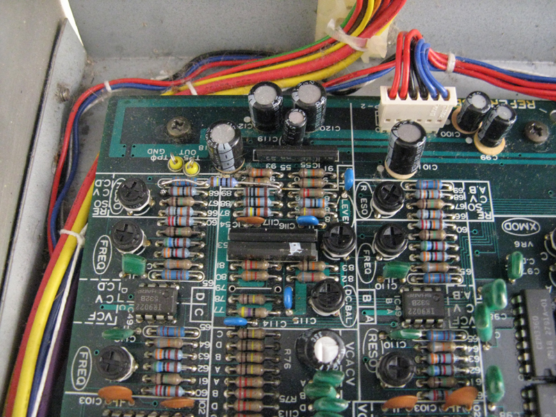
While the standard (logarithmic) VCO-to-VCO-modulation cannot be played tonally, the VCO to VCF modulation can be played tonally and is an increadible enhancement for analogue subtractive synthesizers tonal possibilities. Usually it is dead simple to achieve - also at the JP6:Disconnect R51* (=output of Xmod VCA) from pin 15 IC33 (VCO1)
and connect it to pin 6 of IC48* (=cv summing point for VCF).
see the blue marking in the schematic (882kB)
see
the blue markings in the pcb (2MB)
I tried this one, and it is ok, but finally I preferred the linear VCO FM
*) later models have different partnumbering: R41 to IC49
Modification No.2: Change logarithmic VCO2-to-VC01-modulation to linear FM
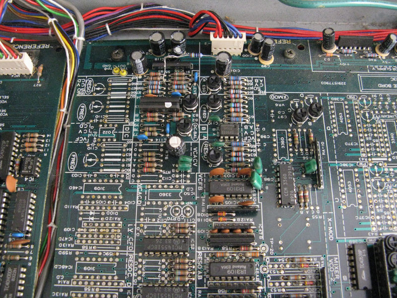
After I had bought my own JP6, I thought about trying the Modification #1. There it came to my mind that the CEM3340 offers a dedicated input for linear FM. So: why not try this one of the Crossmodulation. Brief description:Unsolder R51(older models)/R41(later models) (=output of Xmod VCA) at the side which is connected to pin 15 IC33 (VCO1) and connect it via an additional 68nF capacitor and a resistor in series to pin 13 of IC33. The additional resistor can have a value between 1k and 100k. (in fact you could leave it away, but all modulations above 70% of the total modulation amount become slightly uncontrollable)
see the orange marking in the schematic (882kB)
the changes on the pcb for older models (the orange markings)
the changes on the pcb for newer models
|
I made an soundexample of the modification:
First part: VCO 1 dry with triangle and no FM. beginning with 0:10 I increase the FM Second part (beginning at 0:32): Arpeggio, blending between both dry VCOs with triangle (slightly overdriven, sorry). Then I add the FM. Beginning with 0:47 I lower the VCF cutoff frequency and shorten the filter envelope. Third part: various presets (some delay and reverb added).
|
The vertically standing resistor is the original R41, the red part is the new 68nF capacitor, an the light grey resistor is the new 100k resistor.

This picture shows where the new resistor should be soldered to at the VCO side:

THe next two pictures show the modification at the VCO-A where the placement of R41 is a little bit different:


Modification No.3: Adoption of the signal level to the resonance
One shortcoming of the Jupiter 6 is the behaviour of the resonance in regards of the signal level. As soon as you increase the resonance, the strait signal will seem to be turned down. In fact the technical signal level stays the same, but our hearing does not react like a db-meter. So I thought, that I could simply use the control voltage for the resonance and add a certain amount to it to the VCA which controls the final signal level. I tried it and it worked out to be a quite good workaround.I made an soundexample of the modification.
Brief description:
The mod is a 1MOhm resistor between R62 where it is NOT connected to R61 and the summing point of R81,82,83,84. These are the part numbers for the old version of the JP6.
For the later version of the JP6 the part numbers are "between R68 where it is NOT connected to R67 and the summing point of R86,87,88,89".
On the four voice board, R62/68 exist two times (A and B). You only have to do it here once.

This is the resistor on the two voice pcb. I let the long legs only while the testing. You should shorten them of course to an suitable length.
This is the position for the resistor on the four voice pcb.