Chord-Trigger for Korg Polysix and Poly61 - Manual
WARNING!! THIS MODIFICATIONS REQUIRE TO OPEN THE CASE OF THE SYNTH. THIS SHOULD ONLY BE DONE BY PEOPLE, WHO KNOW HOW TO HANDLE THE DANGEROUS VOLTAGES INSIDE OF THE SYNTH PROPERLY WITHOUT ENDANGERING THE LIFE OF OTHERS OR THEMSELVES!!! IF YOU DON'T HAVE THE REQUIRED EXPERIENCE - KEEP YOUR HANDS OFF!!! DOING THE WRONG THINGS INSIDE AN ELECTRICAL INSTRUMENT MAY KILL YOU OR PEOPLE, THAT RELY ON YOUR WORK. I WARNED YOU. I REJECT ALL LIABILITY FOR ALL CONSEQUENCES OF THE FOLLOWING INSTRUCTIONS!
This manual contains four sections.
- Part one explains how the chord-trigger modification works. May be you know this already
- Part two explains how to build the kit. You may override this part if you ordered the assembled addon pcb.
- Part three describes how the pcb is installed in the Polysix or the Poly61. This has to be done by every user of the chord-trigger mod. So: read this definitely!
- Part four finally explains the function of the adjustable trigger delay and describes how to adjust it. It is not necessary, that you do this, but it may be interesting under some circumstances. So: read this too!
REMARK: I will not explain the basics of doing solderwork in a synth. This addon should be installed of knowledged people. If you do the wrong thing, you will destroy your synth for sure. So hands off, if you are not used to solder inside synths.
1.) The Function of the Chord-Trigger Modification.
Though two microprozessors are working in the Polysix and the Poly61, both are basically analogue synthesizers, where each voice is controlled by a keyboard control voltage and a gate voltage. The keyboard control voltage determines which key has been pressed and it determines the pitch of the corresponding voice; this voltage is set as soon a key has been pressed, and it will stay at the same value even if the key is released. The gate voltage determines whether a key is pressed or not. The gate voltage decides whether there is a sound from this voice or not. No gate, no sound.
The chord trigger mod provides a set of six additional electronic switches which are inserted in the line of the six original gate voltages. The switches are activated by a voltage. As long as there is no cable is inserted in the control input of the chord-trigger, a continuous voltage is fed to the switches. They will be always on. In this case the gate voltage at each voice will represent whether the key is pressed or not - like in an unmodified Polysix or Poly61.
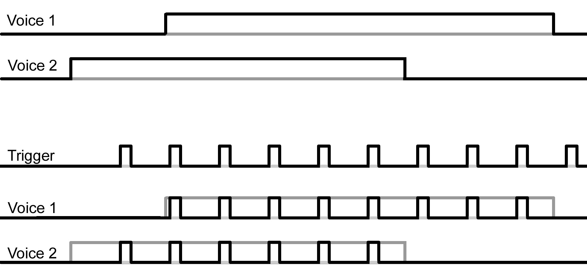
As soon as you insert a cable in the control input, this continous voltage is taken away from the switches, and the switches can be switched on by a trigger-voltage (+5V) coming via the cable - for example from a drum machine, from an analogue synth, or from a MIDI-2-CV/Gate-Interface. The following graph shows how the trigger switches the original gates on and off.
The addon board simply is placed instead of two ICs inside the synth. Those ICs are the gate outputs of the digital circuitry. I moved those ICs to the addon board, and have added two other ICs which act like switches (so called AND functions). The transistors on the addon board prepare and buffer the external trigger signal for the switches. The trimmer provides the possibility of a trigger delay (I will explain this in section 4).
2.) Soldering the kit
First check, whether you have all required parts. The kit requires:
1 pcb
4 screws
4 spacer washers
2 ribbon cables with sockets pressed on
2 simple IC sockets
4 IC sockets industry standard
2 Transistors BC547C
2 Resistors 10k
2 Resistors 47k
2 ICs CD4081
2 ICs HEF40175 or CD4175 (the letters may vary, the numbers are important)
1 Capacitor 4.7nF
1 Trimpotentiometer 250k
2 ribbon cables with sockets pressed on
~1meter (~3ft) of triple wire
1 6.3mm socket
Solder the parts on the pcb on the following order:
- Resistors
- Industry IC sockets in the places for the four ICs (the simple IC sockets are not soldered on the addon pcb! keep them for chapter 3)
- Capacitor
- Transistors
- Trimpotentiometer
Position of the addon pcb in a Polysix
In the Poly61 we will mount the addon pcb at the left side of the CPU board. So the cable should leave the addon pcb at the right side.
Position of the addon pcb in a Poly61
Remove about 3mm of the insulation on both sides of the triple wire. Solder the three wires in the three solder points marked with jp3
Now solder the 6.3.mm socket to the other end of the triple cable.
- The wire coming from the ground pin has to connect to the shaft contact
- The wire coming from the trigger pin has to be soldered to the tip contact
- The wire coming from the +5V pin has to be soldered to the switching contact of the socket.
Insert the ICs into their sockets. Watch out for the right orientation. Pin 1(the notch) is always in the direction of the transistors.
Finally turn the trimm potentiometer fully couter clock wise.
Thats it.
3.) Installing the addon pcb
You need the following tools:- Soldering iron and soldering tin (I recomend plumbed tin).
- desoldering tools (mechanical or electrical pump, mesh)
- fine side cutter pliers or better a micro shear
- a not too big combination pliers
- a needle pliers
- a cross screw driver
- a mid sized flat screw driver (4mm blade)
- a 1,5mm drill
- four toothpicks, needles, thin nails, or simply short pieces of a stiff cable
1 pcb with 2 wide ribbon cables and 1 3-wire ribboncable
4 screws
4 spacer washers
2 simple IC sockets
The procedure is nearly identical for the Polysix and the Poly61, but I will describe it in full length for both synths
3.1.) Polysix
- Place the Synth on its side panel, and look at its wooden bottom plate. Remove the four screws at the rear boarder of the bottom plate. Don't loose these screws.
- Place the Synth normally. Remove the two larger screws on the left and the right side of the front panel.
- Open up the Frontpanel. It will be kept from bending over by a cable that is soldered on the CPU board, but do not stress that cable.
- The large pcb on the right is the voice board. Remove all connectors from this board. The larger ones may be a bit difficult. You may grab them with the combi plier. Pulling first on one end then at the other will help. Perhaps use the flat screw driver as lever.
- The voice board is fixed with five screws on the bottom plate. Remove these screws.
- Pull the board horizontally away from the keyboard. It will slip out of its holding rail under the keyboard. Usually it is not necessary to remove the keyboard (it is kept by six big screws from the bottom side). I took a picture with the keyboard removed, so you can imagine how this holding rail is placed.
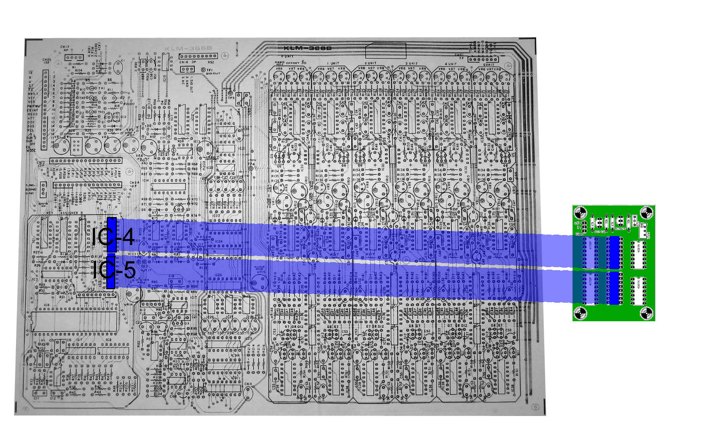
- Now you have to remove the ICs 4 and 5 (see picture 1). I strongly recommend not to desolder them as complete ICs. I think I am quite experienced in desoldering ICs from pcbs, but this Korg pcb was a serious challenge for me. The danger that you rip of a trace from the pcb is big. So please follow the suggested way:
- First cut all pins of the ICs with the micro shear or side cutter,
- Then remove the body of the IC
- Finally remove the individual pins, by heating them at the solder point and then pulling them with the needle pliers.
- After having removed all pins clean the soldering points with the desoldering tool.
- Insert the two simple IC-sockets in place of the ICs and solder them to the pcb
- Now it might be time to add the voice leds as described on my webpage
- Put the pcb back into its position in the synth
- Fasten it with the five screws at the bottom plate
- Reseat all cables again on the pcb
- Place the addon pcb aside the synths pcb. The side with the transistors should point to the rear side of the synth.
- Mark the position of the mounting holes on the wooden bottom plate
- Remove the addon pcb and drill the four holes in the wood
- Place the four toothpicks (of what ever you have) in the holes
- Place the spacer washers over the toothpicks
- Place the pcb over the toothpicks and spacers.
- Remove one toothpick and replace it with a screw. Fasten the screw in the wood.
- Do the same with the other three toothpicks and screws (if you think this procedure is ridiculous, try it without the toothpicks. Maybe you are more ably than me).
- Insert the two ribbon cables coming from the addon pcb into the sockets, that you soldered on the voice board pcb. The cable closer to the transistors goes to the former IC4, the other cable goes to the former IC5.
Now you are basically done. Close the frontpanel of the synth and test it. With no cable inserted in the trigger input, the synth should work normally.
If the first test is successful, then insert a cable to the trigger input, which feeds a voltage-trigger from a drum machine or a gate-signal from a synth or a MIDI-2-CV/Gate interface. Play a chord and send triggers from the external device. Please keep in mind, that many triggers are very short signals. Use the envelope for the VCA, put Attack to 0, Decay and Sustain to maximum and Release to 5.
If this second test is successfull: congratulations! Now continue with closing the synth again or with adjusting the trigger delay, both as described below.
If the first test fails, check whether the ribbon cables are placed correctly and whether the cables are not mismatched. If this does not help you may put the synth back in the original state quite easily (see below).
If the second test is not successful assumingly your trigger signal is not suitable. You may test this like that:
Insert a cable (about 1.5m) in the trigger in socket. Take the other end of the cable and touch with its tip the pin 16 of the HEF40175 (=+5V) on the addon pcb. This should cause a trigger.
Please be aware, that you MUST use a voltage trigger. Any kind of audio signal will NOT work as trigger!
I assume that the test was successful and you did perhaps the adjustment of the trigger delay: so these are the final steps:
- Place the cable from the trigger in socket to the addon pcb at the rear of the ground board. The cable should not run across the pcbs. I recommend to use cable straps to fix it to the other cables. I did not provide a solution, since I don't know, where you are placing the socket.
- You may now adjust the trigger delay (see part 4)
- Close the synths frontpanel
- Fasten the four bigger screws on the frontpanel
- Turn the synth on its side panel
- Fasten the five smaller screws at the bottom
You are done.
Remove the addOn
Switch off the synth. Remove the two new ribbon cables from the voiceboard. Remove the two ICs HEF40175 from the sockets on the addon pcb and place them in the sockets on the voiceboard. The orientation of the ICs stays the same. Switch on the synth and test again. It should act now completely normal.
If not, then you destroyed something while desoldering. Sorry.
3.2.) Poly61
- Place the Synth on its side panel, and look at its wooden bottom plate. Remove the four screws at the rear boarder of the bottom plate. Don't loose these screws.
- Remove the four larger screws at the front, and two same sized screws at both rear ends of the keyboard. Don't loose these screws too. The keyboard now will be loose. So pay attention, that it does not fall out of the synth.
- Place the Synth normally. Remove the two larger screws on the left and the right side of the front panel. And again: don't loose these screws.
- Open up the Frontpanel. It will be kept from bending over by a cable that is soldered on the CPU board, but do not stress that cable.
- The large pcb on the left is the CPU board. Remove all connectors from this board. The larger ones may be a bit difficult. You may grab them with the combi plier. Pulling first on one end then at the other will help. May be it is necessary to use the flat screw driver as lever.
- Now you can remove the keyboard completely.
- The board is fixed on the bottom plate with four screws. Remove
these screws. Don't loose them (I think I mentioned that once already).
- Remove the board.
- Now you have to remove the ICs 9 and 10.
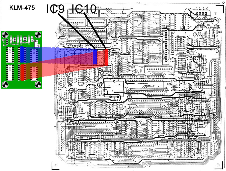
There are at least two variations of the Poly61. In one variation the pcb is labeled "KLM-475": IC 9 and IC 10 are placed both on the main pcb:
In the other (later) variation the pcb is labeled "KLM-509": two cables sit in the place of IC 9. The IC 9 itself sits on a small board on the left of the CPU-pcb:
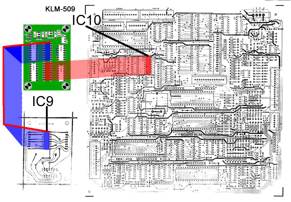
In this case you have to remove the screws of this little pcb too (I won't talk about not loosing screws anymore).
- I strongly recommend not to desolder the ICs as complete chips. I think I am quite experienced in desoldering ICs from pcbs, but those Korg pcbs were a serious challenge for me. The danger that you rip off a trace from the pcb is big. So please follow the suggested way:
- First cut all pins of the ICs with the micro shear or side cutter,
- Then remove the body of the IC
- Finally remove the individual pins, by heating them at the solder point and then pulling them with the needle pliers.
- After having removed all pins clean the soldering points with your desoldering tool.
- Insert the two simple IC-sockets in place of the ICs and solder them to the pcb
- Put the pcb back into its position in the synth.
- Fasten it with the five screws at the bottom plate
- Put the keyboard back into the synth
- Reseat all cables again on the pcb
- Place the addon pcb aside the synths pcb. The side with the transistors should point to the rear side of the synth.
- Mark the position of the mounting holes on the wooden bottom plate
- Remove the addon pcb and drill the four holes in the wood
- Place the four toothpicks (of what ever you have) in the holes
- Place the spacer washers over the toothpicks
- Place the pcb over the toothpicks and spacers.
- Remove one toothpick and replace it with a screw. Fasten the screw in the wood.
- Do the same with the other three toothpicks and screws (if you think this procedure is ridiculous, try it without the toothpicks. Maybe you are more ably than me).
- Insert
the two ribbon cables coming from the addon pcb into the
sockets, that you soldered on the voice board pcb. The cable closer to
the transistors goes to the former IC9, the other cable goes to the
former IC10. Please obey, that the direction of the colour coded cables
should be the same on the addon board and on
the synths pcbs.Especially on the later version with the small extension board this can be mismatched.
Then you have to find a place for the trigger socket. You may drill a hole in the backpanel of the synth, but this is an ugly job. I recommend to remove one of the tape-sockets and use the free hole for the trigger socket. There is still a possibility to use the tape interface (I will write a description soon - if I didn't do, then send me a mail). I leave this up to you.
Now you are basically done. Close the frontpanel of the synth and test it. With no cable inserted in the trigger input, the synth should work normally.
If the first test is successful, then insert a cable to the trigger input, which feeds a voltage-trigger from a drum machine or a gate-signal from a synth or a MIDI-2-CV/Gate interface. Play a chord and send triggers from the external device. Please keep in mind, that many triggers are very short signals. Use the envelope for the VCA, put Attack to 0, Decay and Sustain to maximum and Release to 5.
If this second test is successfull: congratulations! Now continue with closing the synth again or with adjusting the trigger delay, both as described below.
If the first test fails, check whether the ribbon cables are placed correctly and whether the cables are not mismatched. If this does not help you may put the synth back in the original state quite easily (see below)
If the second test is not successful assumingly your trigger signal is not suitable. You may test this like that:
Insert a cable (about 1.5m) in the trigger in socket. Take the other end of the cable and touch with its tip the pin 16 of the HEF40175 (=+5V) on the addon pcb. This should cause a trigger.
Please be aware, that you MUST use a voltage trigger. Any kind of audio signal will NOT work as trigger!
I assume that the test was successful and you did perhaps the adjustment of the trigger delay: so these are the final steps:
- Place the cable from the trigger in socket to the addon pcb at the rear of the ground board. The cable should not run across the pcbs. I recommend to use cable straps to fix it to the other cables. I did not provide a solution, since I don't know, where you are placing the socket.
- You may now adjust the trigger delay (see part 4)
- Close the synths frontpanel
- Fasten the four bigger screws on the frontpanel
- Turn the synth on its side panel
- Fasten the five smaller screws at the bottom
You are done.
How to Remove the Addon
Switch off the synth. Remove the two new ribbon cables from the voiceboard. Remove the two ICs HEF40175 from the sockets on the addon pcb and place them in the sockets on the voiceboard. The orientation of the ICs stays the same. Switch on the synth and test again. It should act now completely normal.
If not, then you destroyed something while desoldering. Sorry.
Part 4 Adjusting the trigger delay.
This one is optional.Why a delay on the trigger? Basically no delay is required on the trigger signal. But if you are using two separate triggers from the same source, one for the arpeggio clock and one for the chord trigger (example: the triggers of HiTom and LoTom on a TR-606), then you will find that the real arpeggio notes come a little later than the incoming triggers. This is normal: the CPU needs a little time to calculate the notes and gates. Usually you won't recognize that. But when you apply the chord trigger on the arpeggio, it will reveal this delay. The chord trigger will always trigger two notes instead of one, because it grabs the end of the old note and the beginning of the new note. In this case you can add a little delay to the chord trigger by turning the multiturn trim potentiometer clockwise until only one note can be heard. (If you own a oscilloscope you may adjust that by comparing the two inputs of one of the AND-Gates, but usually doing this by ear is enough).
Copyright by Florian Anwander, March 2015