The Start/Stop-Trigger is switched on also by this switch, but no cable at the cr78 has to be cut (see next page)
| << previous top next >> |
|
|
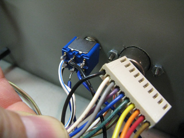
| How to wire the interface: this is the
multipin connector which connects the jack board with the mainboard.
The black wire brings the clock into the mainboard. Unsolder this black
wire from the jack board and solder it to the center pin of the switch.
Solder a new wire from the right pin of the switch to the original
place where the black cable was soldered to the jack board.
Solder another cable from the other pinof the switch to the
Clock-Out-Pin on the new interface_board. The Start/Stop-Trigger is switched on also by this switch, but no cable at the cr78 has to be cut (see next page) |